
SYSTEMS THAT CANNOT STOP.
CONTINUITY IS DESIGNED.
Mission-critical environments demand coordinated protection, visibility, communication and controlled integration across the systems that support continuity.
This field archive documents the physical infrastructure, signal demarcation, early detection technologies, and supervisory interlocks required to isolate risks and protect high-availability environments.
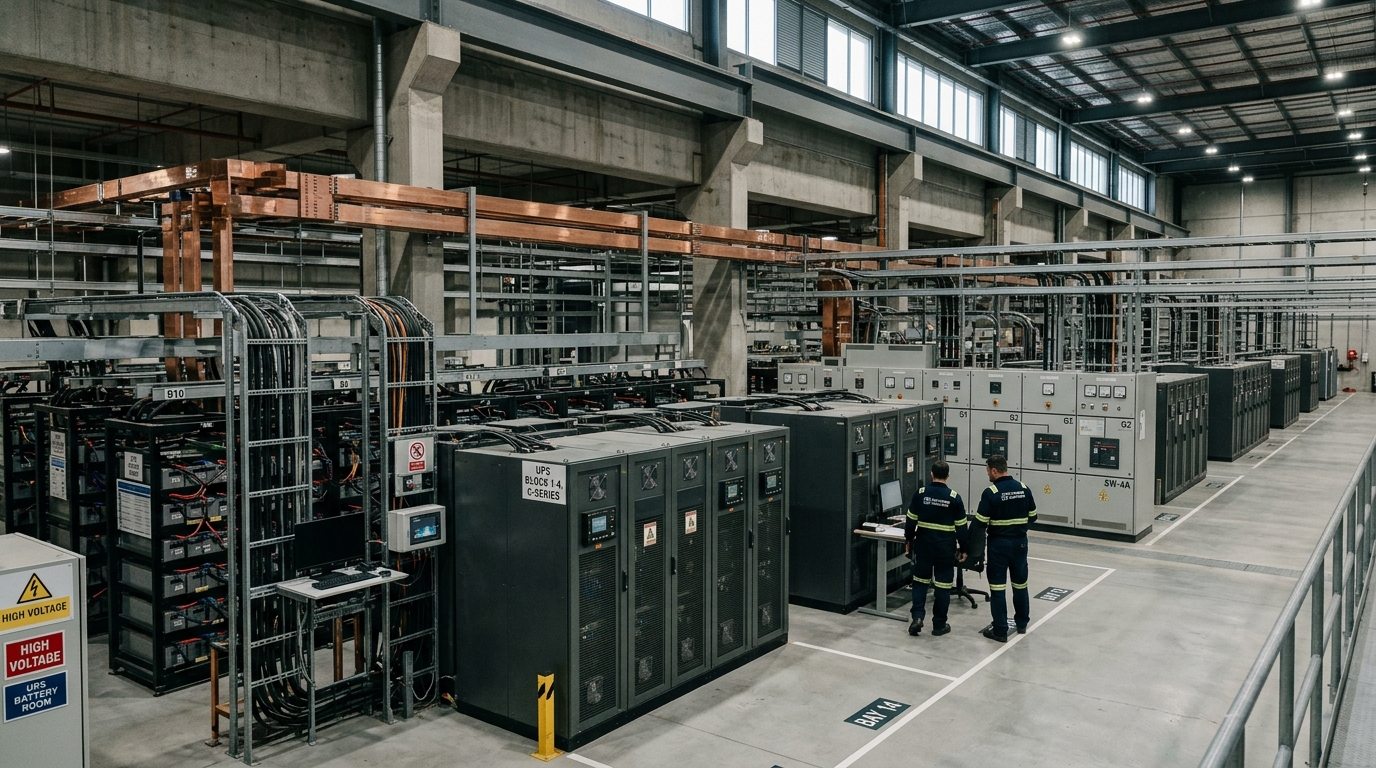
CONTINUITY IS DESIGNED.
Mission-critical environments do not achieve resilience through isolated equipment choices. Uninterrupted operations depend upon multiple engineered disciplines functioning synchronously under rigorous physical, electrical, and operational coordination.
In high-availability facilities—such as enterprise data centers, network operations centers, financial settlement rooms, and command infrastructure—a failure in any single layer must be isolated, annunciated, and mitigated before it can propagate across the operational envelope.
HORNET INFOTECH operates strictly within the ELV / ICT / security / fire / life-safety / communications / monitoring / controls interfaces / systems integration / testing & commissioning / AMC & lifecycle support layer. Project-specific architecture, redundancy levels, and operational performance requirements depend entirely upon the client's engineering design criteria and applicable regulatory standards. HORNET does not independently design structural, architectural, mechanical chiller plant, or primary electrical utility grid systems unless explicitly documented as an interface or monitoring responsibility.
By deploying structured low-voltage cabling, aspirating smoke detection, linear water leak sensing, multi-factor physical access zoning, and open-protocol supervisory interfaces, HORNET delivers the integrated control layer that makes continuous facility awareness possible.
MISSION-CRITICAL REGISTER
DATA CENTRES
Enterprise data halls, colocation suites, hyperscale modular pods
BACnet/IP power monitoring, VESDA aspirating pipe loops, sub-floor WLD cables, biometric mantrap interlocking, aisle-containment CCTV cameras.
Uninterrupted 24/7 continuous operations, strict thermal envelope stability, compartmentalized physical security zones, and zero unverified access events.
SERVER ROOMS
Corporate IT computer rooms, telecom hub enclosures, campus MDF facilities
High-precision dual temperature/RH sensors, spot leak detection probes, clean-agent suppression discharge contacts, rack-level smart card readers.
Continuous ambient environmental verification, immediate notification of liquid or thermal anomalies, and localized access logging.
CONTROL ROOMS
Industrial plant control centers, utility dispatch suites, supervisory command rooms
Multi-screen video wall controllers, low-latency display signal matrices, ergonomic console telemetry buzzers, auxiliary room lighting controls.
High-clarity operator situational awareness, instantaneous alert annunciation, low-strain optical environments, and redundant display sources.
SECURITY OPERATIONS ENVIRONMENTS
Enterprise Security Operations Centers (SOC), central alarm dispatch centers
High-density IP camera decoders, VMS failover recording servers, access control event gateways, emergency panic intercom consoles.
Rapid incident verification, real-time dispatch management, audited chronological video logging, and continuous perimeter alarm visualization.
CRITICAL COMMERCIAL FACILITIES
Financial exchange trading floors, telecommunication switching exchanges, corporate HQs
High-density Category 6A structured cabling, redundant modular UPS serial telemetry, clean-agent status contacts, voice alarm zones.
High-bandwidth communication integrity, zero transactional data loss during power transient, and certified life-safety evacuation routing.
INDUSTRIAL FACILITIES
Continuous processing plants, pharmaceutical cleanrooms, chemical storage complexes
Heavy-duty NEMA/IP-rated DDC enclosures, intrinsically safe sensor loops, toxic/combustible gas detection panels, explosion-proof sounders.
Harsh environment resilience, intrinsic electrical isolation, chemical resistance, and immediate automated hazard containment interlocks.
INFRASTRUCTURE FACILITIES
Transportation terminals, rail traction control nodes, airport baggage/security cores
Single-mode optical ring backbones, industrial Ethernet switches, perimeter barrier telemetry, emergency help points, public address arrays.
Campus-wide survivability, optical loop self-healing resilience, unified perimeter tracking, and high-intelligibility voice messaging.
HIGH-AVAILABILITY OPERATIONAL SPACES
Healthcare emergency diagnostic suites, defense operations rooms, continuity facilities
Isolated power supply telemetry, dedicated emergency intercom lines, tamper-supervised door position contacts, filtered acoustic enclosures.
Stringent access segregation, tamper-evident physical barriers, emergency life-safety coordination, and absolute power distribution monitoring.
REPRESENTATIVE FIELD PLATES
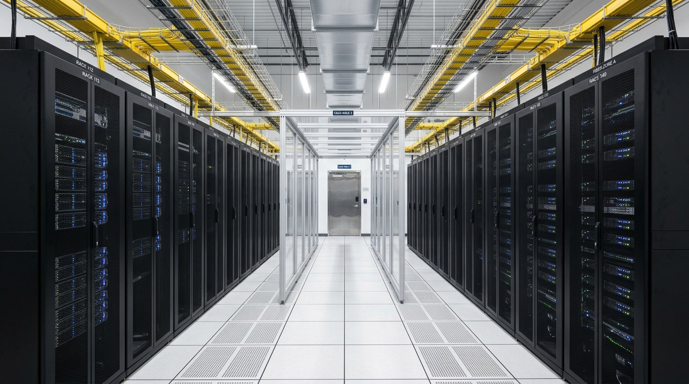
DATA-CENTRE EQUIPMENT ROOM
Controlled mission-critical data hall featuring hot/cold aisle containment, structured high-density optical cable management, overhead containment pathways, and environmental sensor nodes.
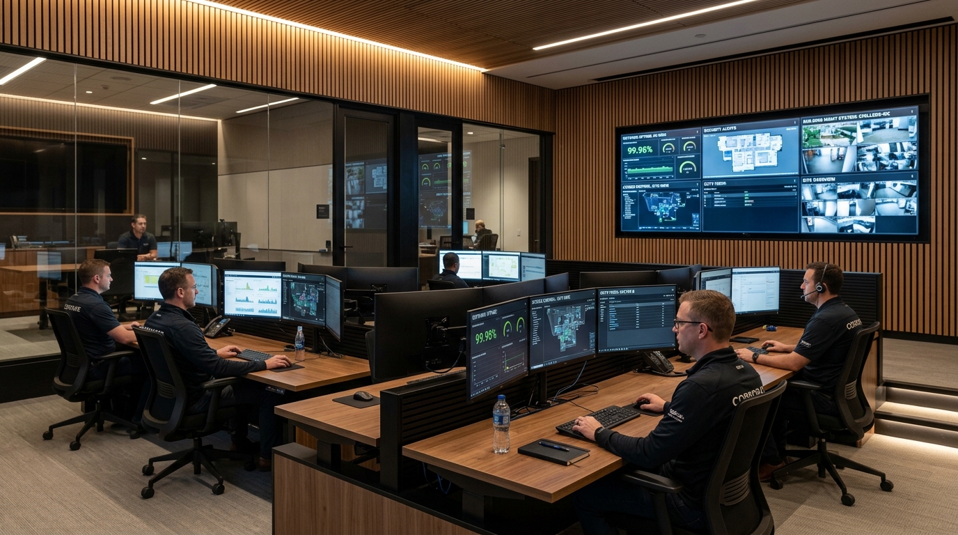
SECURITY & OPERATIONS CONTROL ROOM
Ergonomic command environment equipped with redundant multi-monitor operator consoles, integrated alarm annunciation, facility video matrix switching, and emergency escalation controls.
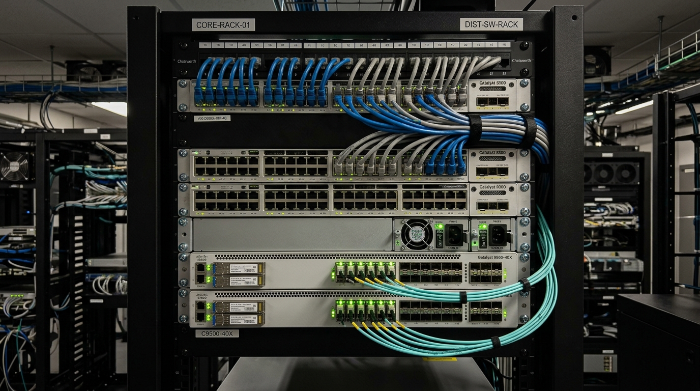
STRUCTURED NETWORK ENVIRONMENT
High-availability networking infrastructure featuring dual physical routing pathways, OM4/OS2 optical terminations, high-density patch fields, and redundant enterprise switching cores.
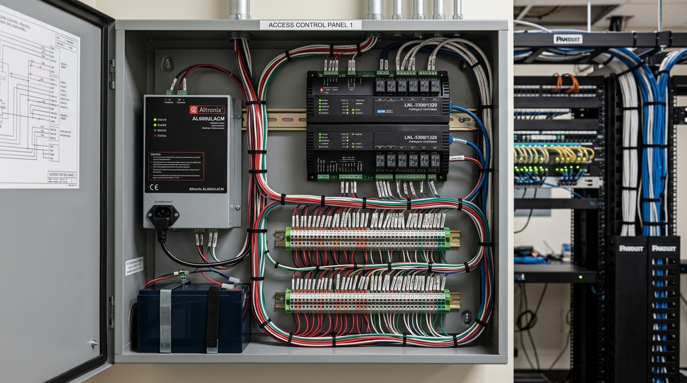
ACCESS-CONTROLLED CRITICAL AREA
Hardened physical access portal utilizing multi-factor credential authentication, high-strength electromagnetic locking with auxiliary monitoring contacts, and optical door sensors.
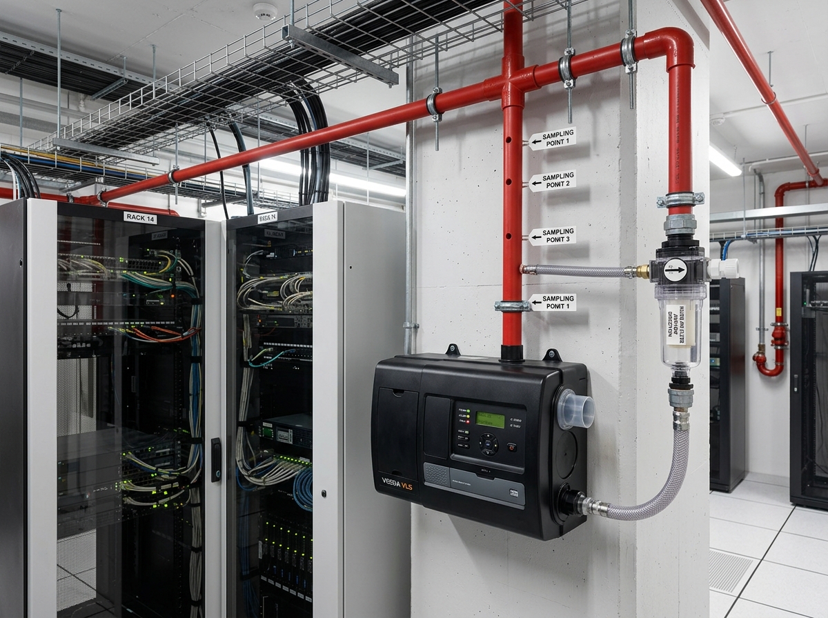
EARLY WARNING FIRE DETECTION
Continuous aspirating smoke detection (VESDA) sampling air within critical equipment rooms and return air paths to identify thermal degradation prior to visible smoke or open flame.
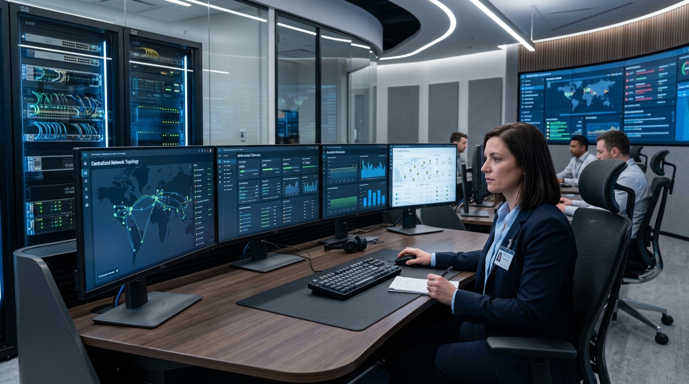
MONITORING & CONTROL INTERFACE
Unified supervisory dashboard aggregating real-time parameters from modular UPS battery strings, precision cooling systems, ambient temperature arrays, and water leak detection loops.
CRITICAL SYSTEMS MATRIX
| SYSTEM | PRIMARY FUNCTION | CRITICAL INTERFACE | TYPICAL MONITORING / RESPONSE |
|---|---|---|---|
CCTV & IP SURVEILLANCE | Continuous visual coverage of perimeter, access portals, equipment corridors, and high-security containment aisles. | RTSP/ONVIF streams, motion analytics triggers, VMS recording server health, storage RAID alerts. | Automated video call-up upon unauthorized card read, long-term audited archival, operator review. |
ACCESS CONTROL | Physical zoning, credential authentication, anti-passback enforcement, and fail-secure locking. | Wiegand/OSDP biometric readers, magnetic lock dry-contacts, door position switches, emergency break-glass. | Instantaneous door-forced alarm, real-time muster roll logging, emergency life-safety unlock interlock. |
FIRE ALARM | Compliant addressable thermal and optical smoke detection across building structural and technical zones. | Supervised FACP alarm contacts, smoke damper command relays, air handler shutdown interlocks. | Municipal notification relay, automatic HVAC shutdown, gas suppression pre-discharge warning. |
VESDA | Very Early Warning Aspirating Smoke Detection sampling air continuous for sub-visible combustion particles. | Laser chamber fault relays, 4-tier alarm contacts (Alert, Action, Fire 1, Fire 2), high-level protocol gateway. | Pre-alarm alert to facilities team before visible smoke occurs, allowing manual investigation prior to gas release. |
WATER LEAK DETECTION | Continuous conductive liquid sensing beneath raised floors, pipe joints, and perimeter walls. | Conductive sensing cable loops, zone monitoring controller relays, Modbus distance-locating output. | Pinpoint meter distance identification on facility floor plan, audible alarm buzzer, facilities dispatch. |
NETWORKING & STRUCTURED CABLING | High-availability physical copper (Cat6A) and single-mode fiber (OS2) distribution backbones. | Managed switch SNMP traps, redundant fiber patch links, patch panel port assignment schedules. | Link loss notification, redundant path rerouting, fiber attenuation loss baseline tracking. |
PA / VOICE EVACUATION | Phased, intelligible emergency voice communication and life-safety evacuation broadcasting. | Supervised 100V speaker line impedance monitors, FACP emergency override trigger, message generator. | Automated zone-by-zone evacuation messaging, manual emergency microphone override, silence control. |
BMS / CONTROL INTERFACES | Supervisory monitoring and parameter collection across connected facility infrastructure. | BACnet/IP, Modbus RTU/TCP gateways, DDC input/output channels, dry-contact status terminals. | Centralized telemetry visualization, out-of-spec alarm thresholds, historical trend logging. |
UPS / POWER MONITORING | Tracking power continuity, battery string health, load balance, and bypass mode status. | SNMP network cards, Modbus multi-function power meters, auxiliary breaker trip contacts. | Utility grid failure notification, battery autonomy countdown calculation, load shed confirmation. |
SECURITY ALARM / INTRUSION | Perimeter barrier protection, vibration sensing, and unauthorized enclosure breach detection. | Supervised end-of-line (EOL) loop resistors, dual-tech PIR/microwave sensors, tamper switches. | Immediate SOC operator alert, audible perimeter deterrent activation, automated camera PTZ preset call. |
CONTINUITY ARCHITECTURE
Signal integrity and operational visibility flow through structured physical and logical layers. The architecture below illustrates typical bidirectional communication and control relationships across a hardened environment.
CRITICAL ENVIRONMENT
Physical spaces containing primary revenue, computing, or operational assets exposed to environmental, electrical, or physical intrusion vectors.
FIELD DEVICES
Transducers and contact switches that convert physical parameters (temperature, liquid presence, combustion aerosols, door contacts) into electrical signals.
LOCAL CONTROL / PANELS
Microprocessor controllers executing localized autonomous logic, fail-safe interlocking, battery backup operation, and digitizing field signals.
NETWORK / COMMUNICATION LAYER
Redundant high-speed communication transport segregating life-safety, security video, and building management protocols into dedicated broadcast domains.
SUPERVISORY / MONITORING LAYER
Central computing engines polling field controllers, reconciling events across subsystems, maintaining auditable logs, and rendering dynamic floor plans.
OPERATOR / FACILITY TEAM
Trained operational personnel receiving prioritized alerts, performing manual incident verification, directing maintenance teams, and executing incident protocols.
CRITICAL FACILITY ZONES
SERVER / IT ROOM
VESDA aspirating smoke detection, raised-floor sensing cable WLD, temperature & humidity sensors, rack door position switches.
Laser detector relays, Modbus distance-locating leak controller, dual temp transmitters, smart card rack locks.
Provide high-density computing containment with early detection of combustion, moisture, and unauthorized server enclosure access.
UPS / ELECTRICAL INTERFACE ZONE
Modular UPS system running parameters, battery string ambient temperature, main ACB trip auxiliary contacts, hydrogen gas build-up.
RS-485 Modbus serial loops, dry contact fault relays, battery monitoring sensors, hydrogen sniffer transmitters.
Verify power conversion continuity, battery autonomy readiness, and detect thermal runaway in high-capacity energy storage banks.
CONTROL / MONITORING ROOM
Room ambient temperature, power feed redundancy, operator access credentials, KVM matrix communication links.
Environmental room transducers, ATS status contacts, access control card reader, console audio alarm buzzers.
Maintain continuous operational comfort, ergonomic console lighting, and uninterrupted supervisory workstation power.
SECURE ACCESS ZONE
Biometric fingerprint/iris readers, interlocking mantrap doors, emergency door release break-glass, tailgating optical sensors.
OSDP encrypted reader channels, door position magnetic switches, electromagnetic lock auxiliary feedback, CCTV call-up triggers.
Enforce strict single-person authentication, eliminate tailgating, and prevent simultaneous opening of interlocking security doors.
EQUIPMENT CORRIDORS
Fixed optical CCTV camera streams, PIR motion detectors, emergency exit door switches, linear heat detection on cable trays.
IP camera network streams, alarm panel supervised loops, emergency egress release switches, voice evacuation speakers.
Track personnel transit between operational modules, verify authorized service presence, and ensure clear emergency egress.
COMMAND / OPERATIONS AREA
Video wall processor status, redundant audio DSP engines, multi-agency communication bridges, incident recording servers.
AVoIP streaming encoders, network matrix switches, emergency panic triggers, recording audit trail logs.
Facilitate high-level incident command, executive briefing, crisis coordination, and comprehensive operational debriefs.
SERVICE / MAINTENANCE ZONE
Tool store access card readers, spare parts inventory RFID sensors, hazardous material cabinet exhaust flow, water sump levels.
Airflow differential pressure switches, liquid level float switches, access control door readers, dry contact alarm inputs.
Manage contractor transit, monitor mechanical drainage, and supervise maintenance tool custody in critical plant spaces.
CRITICAL EQUIPMENT AREA
Clean-agent gaseous fire suppression cylinders, discharge pressure switches, room integrity motorized dampers, pre-discharge warning strobes.
Supervised actuator solenoid coils, cylinder pressure gauges with low-pressure contacts, damper limit switches, warning signs.
Isolate electrical fires through total-flooding clean-agent extinguishing without leaving conductive or corrosive residue on electronics.
LAYERED PROTECTION ARCHITECTURE
DETECT
Continuous atmospheric, physical, and electrical sampling to identify threshold deviations at the earliest possible moment.
VERIFY
Automated correlation of secondary sensors or video imagery to confirm true threat conditions and prevent false alarm propagation.
CONTROL ACCESS
Physical containment of zones to restrict unauthorized entry or automatically unlock emergency egress pathways in verified life-safety events.
COMMUNICATE
Clear, high-intelligibility transmission of incident directives, pre-recorded warning tones, and automated engineering notifications.
ESCALATE
Structured escalation protocols alerting facilities management, on-call technicians, or external emergency responders based on severity.
RESPOND
Physical mitigation actions executed according to approved engineering cause-and-effect designs and statutory life-safety protocols.
MONITOR / RECORD
Immutable, time-stamped digital recording of every signal, operator action, sensor reading, and system transition for compliance audit.
REDUNDANCY & RESILIENCE RECORDS
SYSTEM AVAILABILITY
- Redundant secondary power supply feeds to all ELV control enclosures.
- Autonomous distributed controller logic maintaining local operation during server offline state.
- Hardware watchdog timers automatically rebooting unresponsive microprocessors.
CONTROLLED FAILURE MODES
- Fail-safe release of designated egress doors upon confirmed FACP fire alarm.
- Fail-secure magnetic locking on high-security vaults during total power loss.
- Spring-return motorized dampers defaulting to closed fire-containment orientation.
NETWORK RESILIENCE
- Dual redundant fiber optic backbones routed through geographically segregated risers.
- Rapid Spanning Tree (RSTP) / MRP ring convergence restoring link failures in milliseconds.
- Dedicated VLAN segmentation isolating security video bandwidth from critical telemetry.
EQUIPMENT SEGREGATION
- Physical separation between high-voltage power conduits and sensitive ELV data cabling.
- Segregated marshalling cabinets for life-safety, BMS automation, and access control.
- Class A signaling circuits routing return loops through separate physical raceways.
MONITORING CONTINUITY
- Dual-homed supervisory servers synchronizing real-time databases and alarm queues.
- Non-volatile flash memory inside field DDCs buffering historical trends during network partition.
- Local audible and visual annunciators on panel exteriors independent of network status.
ALARM VISIBILITY
- Hierarchical alarm prioritization filtering non-critical warnings during major incidents.
- Multi-screen SOC layouts dedicating persistent displays to unacknowledged life-safety alerts.
- Visual floor plan flashing markers highlighting exact spatial location of sensor triggers.
MAINTENANCE ACCESS
- Isolating terminal disconnect blocks enabling sensor replacement without panel power down.
- Bypass test switches for smoke dampers and suppression actuators during scheduled testing.
- Front-access 19-inch rack mounting minimizing rear clearance service interruptions.
LIFECYCLE SUPPORT
- Scheduled sensor recalibration protocols for humidity, gas, and temperature transducers.
- Version-controlled software and firmware backup repositories stored off-site.
- Contractual AMC preventative inspections ensuring adherence to original commissioning benchmarks.
INTEGRATION INTELLIGENCE RECORDS
The four representative cause-and-effect records below demonstrate coordinated multi-system reaction pathways. All emergency sequences are strictly subordinate to approved fire engineering guidelines and statutory life-safety mandates.
FIRE DETECTION & SUPPRESSION COORDINATION
VESDA or cross-zoned addressable smoke detectors verify combustion particles in a server hall. The fire panel initiates pre-discharge sounders, signals the BMS to close smoke dampers and shut down AHUs, holds doors on electromagnetic retainers, discharges clean agent following time delay, and records exact chronological timestamps in the system log.
SUB-FLOOR WATER LEAK LOCALIZATION
Conductive fluid breaches a raised-floor cooling manifold. The sensing cable loop experiences a change in circuit resistance. The localized controller calculates distance down the cable, triggers an audible warning, transmits distance coordinates to the BMS floor plan, notifies the facility duty engineer, and dispatches maintenance personnel.
UNAUTHORIZED ACCESS & PERIMETER CORRELATION
A monitored mantrap door is forced open without a valid credential read. The magnetic position switch changes state, the door controller generates an instant tamper alert, the VMS directs nearby PTZ cameras to orient toward the door, the SOC display highlights the incident on the visual map, and high-framerate recording begins.
CRITICAL POWER TELEMETRY ANOMALY
A digital power meter on an essential busway detects severe voltage harmonic distortion or a sudden phase imbalance. Modbus registers poll the out-of-spec parameter, the BMS flags an impending power anomaly, the duty engineer evaluates battery string load, and proactive diagnostics prevent unexpected circuit breaker tripping.
TECHNICAL RECORD DELIVERABLES
DEVICE SCHEDULES
Itemized schedules enumerating every deployed camera, smoke sensor, card reader, and WLD probe with part numbers and locations.
POINT SCHEDULES
Hardware and software I/O registers mapping sensor loop addresses, controller channel pins, and supervisory SCADA tags.
NETWORK ARCHITECTURE
Topological diagrams illustrating core and distribution switches, optical backbones, VLAN IDs, and IP addressing schemas.
INTERFACE MATRICES
Demarcation documentation defining physical and logical boundaries between ELV systems, chillers, UPS, and fire panels.
CAUSE & EFFECT MATRICES
Detailed behavioral tables documenting interlocks, fan shutdowns, gas releases, door unlocks, and alarm notification rules.
SYSTEM SCHEMATICS
Single-line riser schematics depicting signal conduits, power distribution feeds, and communication loops across floors.
PANEL SCHEDULES
Internal general arrangement (GA) drawings showing DIN-rail components, power supplies, circuit breakers, and terminal blocks.
CABLE & CONNECTIVITY RECORDS
Fluke calibration certification reports, optical OTDR trace tests, and comprehensive patch-field termination schedules.
TESTING RECORDS
Pre-commissioning loop check sheets, sensor trigger calibration certificates, and battery autonomy verification logs.
COMMISSIONING RECORDS
Integrated systems testing (IST) sign-offs, full-scale power failover simulation results, and statutory witness reports.
AS-BUILT DOCUMENTATION
Final certified AutoCAD as-built drawings detailing exact physical raceway locations, cable paths, and panel coordinates.
AMC / LIFECYCLE RECORDS
Preventative maintenance schedules, sensor recalibration logs, firmware update checklists, and emergency response procedures.
CRITICAL ENVIRONMENT BASELINE
ENVIRONMENT CLASSIFICATION
Assessment of ambient thermal envelope, humidity ranges, airborne particulate levels, electromagnetic interference (EMI), and seismic zone factors.
SYSTEM CRITICALITY
Determination of downtime financial impact, life-safety implications, regulatory compliance penalties, and acceptable recovery time objectives.
ACCESS HIERARCHY
Definition of concentric physical security zones, multi-factor credential requirements, anti-passback rules, and visitor escort constraints.
MONITORING REQUIREMENTS
Specification of continuous polling intervals, high-resolution trend storage, sensor accuracy tolerances, and alarm priority stratification.
COMMUNICATION TOPOLOGY
Selection of physical cable pathways, single-mode optical rings, industrial Ethernet switch resilience, and network protocol encryption standards.
EQUIPMENT LOCATION
Verification of floor load capacity, water source clearance, cooling airflow paths, service clearance access, and physical tamper protection.
MAINTAINABILITY & SERVICING
Inclusion of modular isolation switches, test bypass loops, clear terminal labeling, and comprehensive spare part availability.
ALARM VISIBILITY & ESCALATION
Ergonomic display formatting, multi-screen console layout routing, audible warning frequencies, and automated notification duty rosters.
INTERFACE DEPENDENCIES & CODES
Reconciliation of electrical switchgear, MEP chiller systems, statutory fire regulations (NBC/NFPA), and proprietary manufacturer protocols.
ENGINEERED SYSTEMS
CCTV & IP Surveillance
Continuous visual perimeter & containment coverage.
Access Control & Door Access
Biometric portals, mantrap interlocking & door security.
Fire Alarm Systems
Addressable detection loops & emergency interlocks.
Structured Cabling & Fibre Optics
Category 6A copper & single-mode optical backbones.
Networking & Infrastructure
Enterprise managed switching & redundant routing.
Data Centres & Hub Rooms
High-density containment & environmental telemetry.
Online Modular UPS & Power
Modular power continuity & battery monitoring.
VESDA Aspirating Detection
Early warning air-sampling detection for critical rooms.
Water Leak Detection (WLD)
Conductive sensing cables beneath raised floors.
PA & Voice Alarm Systems
Phased life-safety emergency voice evacuation.
BMS & Building Automation
Supervisory monitoring & DDC panel integration.
AMC & Lifecycle Support
Contractual 24/7 preventative maintenance & SLA.
RELATED DISCIPLINE ARCHIVES
SECURITY & ACCESS
Access control matrices, IP surveillance clusters, speed gates, and SOC environments.
FIRE & LIFE SAFETY
Addressable detection loops, clean-agent suppression, VESDA, and voice alarm evacuation.
NETWORK & DATA
Structured Cat6A copper cabling, single-mode optical backbones, and enterprise routing.
DATA CENTRES & HUB ROOMS
Whitespace containment, modular online UPS, environmental monitoring, and WLD.
AV / VIDEO WALLS / CONFERENCING
SOC display walls, boardrooms, conferencing codecs, and digital signal processors.
BMS & AUTOMATION
Centralized facility telemetry, DDC automation panels, and multi-discipline integration.
VERIFIED MISSION-CRITICAL PROJECT RECORDS
Documented mission-critical ELV, electronic security, life safety, and network cabling infrastructure delivered and commissioned under strict confidentiality governance.
DOCUMENTATION
Compilation of signed commissioning certificates, single-line schematics, and equipment registers upon operational handover.
TECHNICAL VERIFICATION
Internal engineering audit verifying as-built accuracy, interface boundaries, and subsystem scope demarcation.
CLIENT CLEARANCE
Formal client security review and redaction of sensitive identifiers, asset tags, and proprietary network addresses.
PUBLICATION
Release of declassified dossier into the public Hornet Infotech Project Archive with permanent archival indexing.
AL-Karim University Campus ICT & ELV Infrastructure
Turnkey campus-wide ELV and ICT infrastructure across the 55-acre AL-Karim University campus in Katihar, Bihar, encompassing approximately 450–500 km of structured cabling, 35 km fibre infrastructure, 1,800+ data points, 1,000+ wireless access points, 500+ IP telephony endpoints, 8 flap barriers, data centre setup, AV conferencing, and environmental detection systems (VESDA, water leak detection, rodent detection).
eClerx Corporate Facility ELV & ICT Infrastructure (Phase 1)
Integrated ELV, electronic security, life safety, and network cabling infrastructure deployed for eClerx Chandigarh (Phase 1), supporting 216 CCTV surveillance cameras, a 340-device addressable fire alarm system, 170 PA speakers/units, 30 access-controlled doors, 1,500+ structured cabling data points, Novec clean-agent suppression, VESDA, WLD, and rodent detection.
eClerx Corporate Facility ELV & ICT Infrastructure (Phase 2)
Integrated ELV, electronic security, life safety, and network cabling infrastructure deployed for eClerx Chandigarh (Phase 2), supporting 178 CCTV surveillance cameras, a 215-device addressable fire alarm system, 120 PA speakers/units, 23 access-controlled doors, 1,000+ structured cabling data points, Novec clean-agent suppression, VESDA, WLD, and rodent detection.
NO SYNTHETIC PROJECT RECORDS
In accordance with HORNET INFOTECH's data governance covenants, zero mock project entries or speculative installation claims are published. Verified client case studies enter the public archive only following completed declassification and client clearance.
REQUEST TECHNICAL CONSULTATION
Engage Hornet Infotech engineering specialists for technical review, system architecture, redundancy planning, or interface specifications for high-availability environments.