
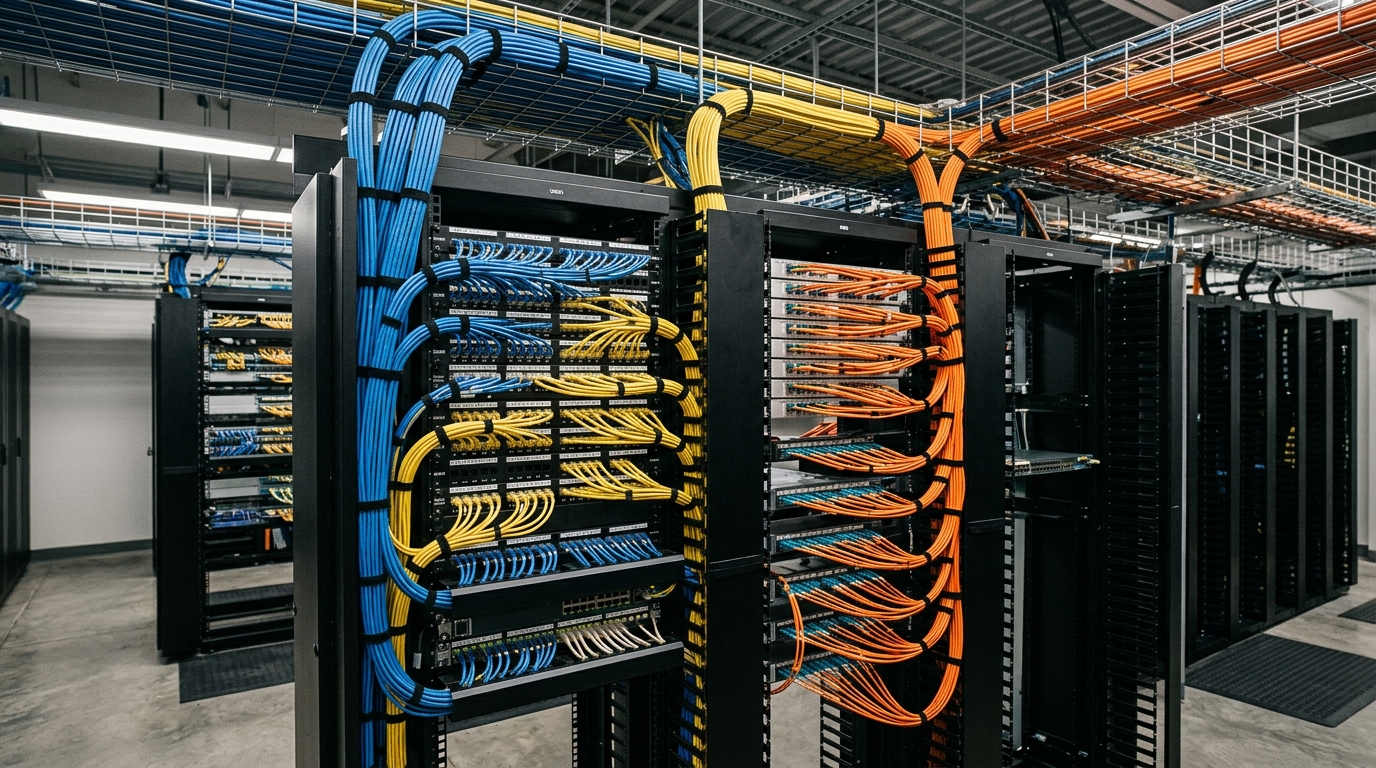
CONNECTED INFRASTRUCTURE.
ENGINEERED FOR FLOW.
A dedicated field archive for structured cabling, fibre-optic infrastructure, network systems and the physical ICT infrastructure that connects enterprise environments.
INFRASTRUCTURE BEHIND THE CONNECTION
Physical ICT systems form the durable, silent foundation beneath every digital transaction, facility sensor, and collaborative communication channel.
Behind high-speed corporate networking, enterprise Wi-Fi clusters, unified surveillance streams, and modern building automation lies an engineered physical layer. Copper structured cabling, high-core optical fibre links, dedicated pathways, precision rack layouts, and telecommunications rooms must be planned with rigorous attention to bandwidth headroom, electrical separation, thermal load dissipation, and lifecycle flexibility.
HORNET INFOTECH focuses on physical infrastructure engineering and integration: establishing robust horizontal copper distributions, single-mode and multi-mode optical campus backbones, overhead wire basket and underfloor tray pathways, standardized MDF and IDF hub rooms, and systematic cable management architectures.
ENGINEERING BOUNDARY NOTICE: Physical ICT infrastructure engineering governs physical pathways, structured media, rack integration, and passive/active link connectivity. HORNET does not claim responsibility for software applications, external cloud services, or client cybersecurity operations unless expressly within contract scope.
NETWORK INFRASTRUCTURE REGISTER
An editorial register of the physical ICT and networking infrastructure systems engineered, terminated, and integrated by HORNET INFOTECH. Subsystem deployment conforms to site architectural conditions and client technical briefs.
STRUCTURED CABLING
Copper horizontal distribution, patching and structured pathways.
FIBRE OPTICS
Fibre backbone infrastructure, termination and optical connectivity.
NETWORK INFRASTRUCTURE
Switching infrastructure, rack integration and network connectivity.
MDF / IDF / HUB ROOMS
Physical ICT rooms, racks, patching and infrastructure organization.
TESTING & DOCUMENTATION
Copper and fibre testing, documentation and handover records as applicable.
REPRESENTATIVE FIELD PLATES
Visual reference plates demonstrating typical structured cabling pathways, fibre backbone terminations, telecommunication rooms, and rack patching infrastructure. Photographic assets serve strictly as illustrative art direction and do not represent documented client installations.
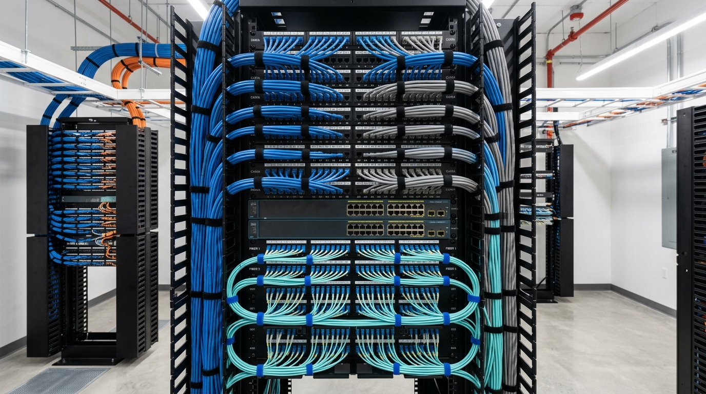
Overhead wire mesh tray containment routing high-density Cat6A U/UTP and F/UTP horizontal cabling bundles with disciplined bend radii and velocity separators.
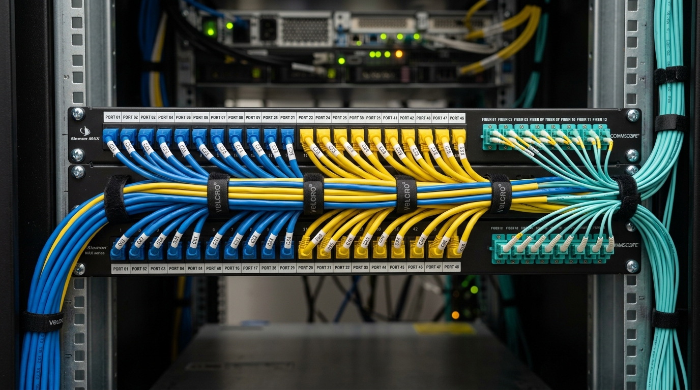
High-density rack-mount optical distribution frames (LIU), LC/MPO duplex patch cords, fusion-spliced pigtails, and low-loss optical interconnects.
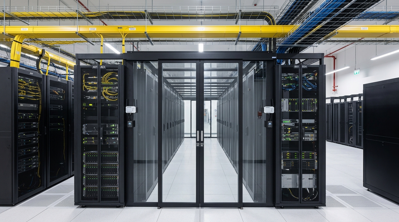
Intermediate and main distribution frame environment featuring uniform 42U equipment enclosures, thermal management, dedicated busbar grounding, and isolated UPS feeds.
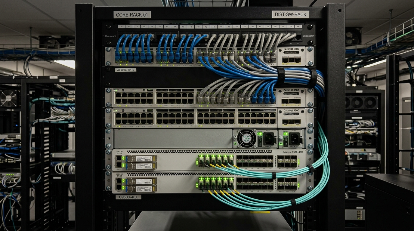
Structured 24-port / 48-port modular patch panels with 1U horizontal and vertical cable organizers, color-coded patch cords, and systematic ANSI/TIA alpha-numeric labelling.
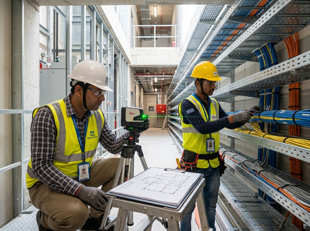
On-site installation disciplines encompassing precision cable pulling tension control, modular keystone jack punch-downs, fire-stop seal penetration collars, and testing execution.
ENGINEERING SCOPE
The technical delivery matrix below outlines HORNET INFOTECH's lifecycle engineering capabilities across physical ICT infrastructure stages. Scope deliverables are project-specific and determined by engineering contracts.
SITE SURVEY & ENGINEERING
Architectural route inspection, horizontal copper distance validation, riser shaft vertical penetration reviews, and core telecommunications room dimensioning.
PATHWAY / CONTAINMENT COORDINATION
Cross-trade coordination for overhead wire basket trays, underfloor trunking, conduit sizing, electromagnetic interference (EMI) isolation, and fire-stop sleeves.
SYSTEM DESIGN
Preparation of structured cabling single-line schematics, rack elevation drawings, optical link budget calculations, and alphanumeric port numbering schemes.
MATERIAL & EQUIPMENT SELECTION
Evaluation of enterprise copper cables (Cat6/Cat6A), low-smoke zero-halogen (LSZH) sheaths, high-grade optical fiber cores, and modular patch equipment.
SUPPLY & INSTALLATION
Installation of pathway brackets, cable tray networks, controlled tension cable pulls, vertical optical riser drops, and structural rack frame assemblies.
TERMINATION & PATCHING
High-density keystone jack terminations, fusion splicing of optical pigtails into LIU enclosures, color-coded patch cord dress, and wire management dressing.
TESTING / CERTIFICATION
Copper and fibre link testing / certification as applicable to design specifications, validating continuity, wire map, insertion loss, and optical attenuation.
DOCUMENTATION & HANDOVER
Compilation of comprehensive as-built CAD drawings, detailed port patching schedules, optical core assignment tables, and structured operational handover registers.
AMC / LIFECYCLE SUPPORT
Ongoing MAC (Moves, Adds, and Changes) support, optical cleaning and OTDR fault localization, structured rack re-dressing, and SLA break-fix attendance.
PHYSICAL INFRASTRUCTURE ARCHITECTURE
A diagrammatic mapping of physical ICT transport from edge work area outlets to core switching and facility-wide systems. This represents physical infrastructure engineering and passive/active interconnectivity.
USER / DEVICE
Workstations, enterprise IP phones, Wi-Fi access points, CCTV cameras, and IoT sensors.
HORIZONTAL CABLING
4-pair Cat6 / Cat6A balanced copper drops run via overhead basket trays and conduits (≤90m).
TELECOM ROOM
Floor IDF rack enclosure housing patch panels, horizontal wire managers, and edge switches.
BACKBONE FIBRE
Multi-strand single-mode (OS2) or multi-mode (OM4) vertical optical riser cable backbone.
MDF / CORE
Main distribution frame with high-density optical LIUs, cross-connect fields, and power UPS.
NETWORK INFRASTRUCTURE
Core routing engines, distribution switch stacks, redundant SFP+ uplinks, and VLAN gateways.
FACILITY SYSTEMS
Connection to enterprise servers, telecom carrier demarcation, BMS, CCTV VMS, and AV codecs.
The physical infrastructure flow mapped above illustrates the structured media hierarchy engineered and deployed by HORNET INFOTECH. This architectural layer provides reliable, standards-based physical connectivity. HORNET does not manage customer software applications, internal active directory/cloud services, or customer cybersecurity policies unless explicitly specified in contractual scopes.
REPRESENTATIVE FACILITY ZONES
An architectural spatial matrix profiling typical facility zones and their corresponding physical ICT infrastructure requirements. Specific topologies and bill of materials remain tailored to project contracts.
MAIN DISTRIBUTION FRAME / CORE
INTERMEDIATE DISTRIBUTION FRAME
SERVER / NETWORK ROOM
OFFICE / WORKPLACE AREAS
MEETING / COLLABORATION AREAS
CAMPUS / BUILDING BACKBONE
SECURITY / ELV NETWORK INTERFACE
SERVICE / TELECOM PATHWAYS
THE RECORD IS PART OF THE SYSTEM
In physical ICT infrastructure engineering, an undocumented cable is a future operational outage. Rigorous port schedules, cable schedules, optical core mapping, and as-built line schematics constitute permanent project capital.
Testing procedures and handover documentation packages are compiled strictly as applicable to verified project records.
HORNET does not publish synthetic test results, fabricated decibel loss values, artificial OTDR traces, or hypothetical certification logs.
CABLE SCHEDULES & ROUTE CHARTS
Comprehensive tabular records logging cable unique identifiers, originating patch panel port, intermediate pathway reference, terminal faceplate location, and measured length.
PORT SCHEDULES & SWITCH MAPS
Port-by-port cross-connect matrices linking horizontal patch panel ports to active switch ports, VLAN assignments, PoE wattage budgets, and designated user or device endpoints.
RACK ELEVATIONS & POWER BUDGETS
Dimensional CAD front and rear rack elevations showing exact unit positions (1U to 42U), cable manager placements, PDU distribution circuits, and thermal airflow pathways.
FIBRE-CORE DOCUMENTATION & SPLICE CHARTS
Color-coded optical core assignment tables documenting tube numbers, strand color sequence, fusion splice tray locations, LIU coupler assignments, and optical attenuation records.
TEST RECORDS & CERTIFICATION REPORTS
Electronic test export binders compiling copper permanent link / channel tests and optical power meter/OTDR loss measurements as required by project specifications.
STANDARDIZED LABELLING & AS-BUILT DRAWINGS
Thermal-transfer machine-printed labels matching CAD floor plans with unambiguous room-rack-panel-port alphanumeric syntax applied across all cords, panels, and outlets.
VERIFIED NETWORK & DATA PROJECT RECORDS
Documented structured cabling, optical fibre backbones, campus networking, and enterprise physical ICT infrastructure delivered, certified, and handed over under formal contract governance.
AL-Karim University Campus ICT & ELV Infrastructure
Turnkey campus-wide ELV and ICT infrastructure across the 55-acre AL-Karim University campus in Katihar, Bihar, encompassing approximately 450–500 km of structured cabling, 35 km fibre infrastructure, 1,800+ data points, 1,000+ wireless access points, 500+ IP telephony endpoints, 8 flap barriers, data centre setup, AV conferencing, and environmental detection systems (VESDA, water leak detection, rodent detection).
eClerx Corporate Facility ELV & ICT Infrastructure (Phase 1)
Integrated ELV, electronic security, life safety, and network cabling infrastructure deployed for eClerx Chandigarh (Phase 1), supporting 216 CCTV surveillance cameras, a 340-device addressable fire alarm system, 170 PA speakers/units, 30 access-controlled doors, 1,500+ structured cabling data points, Novec clean-agent suppression, VESDA, WLD, and rodent detection.
eClerx Corporate Facility ELV & ICT Infrastructure (Phase 2)
Integrated ELV, electronic security, life safety, and network cabling infrastructure deployed for eClerx Chandigarh (Phase 2), supporting 178 CCTV surveillance cameras, a 215-device addressable fire alarm system, 120 PA speakers/units, 23 access-controlled doors, 1,000+ structured cabling data points, Novec clean-agent suppression, VESDA, WLD, and rodent detection.
In accordance with HORNET INFOTECH's data governance covenants, zero mock project entries or speculative installation claims are published. Verified field documentation dossiers are published under formal non-disclosure clearance.
Engineering designs reflect client site constraints, architectural layouts, and functional specifications.
Standards references applied where contractually stipulated by project tender documentation.
Horizontal media, optical strand counts, and containment routes engineered per facility geometry.
Permanent link, channel, and optical attenuation testing conducted as mandated by contract scope.
ENGINEERED SYSTEMS
Review detailed equipment specifications, engineering criteria, and subsystem topologies on HORNET INFOTECH's canonical solution dossiers.
Structured Cabling & Fibre Optics
High-density Cat6A copper networks, single-mode optical backbones, modular patch frames, and wire basket containment.
Networking Infrastructure
Core, aggregation, and access layer switching architectures, PoE+ power distribution, and SFP+ optical uplink matrices.
Hub Rooms & Data Centres
MDF and IDF technical room fitout, 42U equipment enclosures, thermal management, busbar earthing, and rack UPS isolation.
RELATED FIELD ARCHIVES
IP surveillance, controlled portals, speed turnstiles, and perimeter physical defense systems.
FIELD RECORD / 04DATA CENTRES & HUB ROOMS →Precision white space, power distribution, thermal containment, and infrastructure monitoring.
FIELD RECORD / 05AV & VIDEO WALLS →Executive boardroom codecs, narrow-bezel SOC video walls, and high-performance AVoIP matrices.
FIELD RECORD / 07MISSION-CRITICAL INFRA →High-availability 2N power isolation, clean-agent suppression, and continuous uptime facilities.
PUBLICATION PIPELINE
DOCUMENTATION
Collection of as-built CAD files, copper and optical test summaries, single-line diagrams, and equipment manifests from site engineering teams.
TECHNICAL VERIFICATION
Independent internal engineering audit validating that documented cable categories, optical attenuation, and equipment schedules match verified physical delivery.
CLIENT CLEARANCE
Formal legal review ensuring full compliance with non-disclosure agreements, redacting sensitive proprietary floor plans, room identifiers, and IP addressing schemes.
PUBLICATION
Formal entry of the redacted, verified engineering dossier into the public HORNET INFOTECH field archive repository.
HORNET INFOTECH
Consult with our engineering team for structured cabling architectures, campus fibre backbones, MDF/IDF technical room layouts, and physical ICT infrastructure projects.