
BUILDING SYSTEMS.
WORKING TOGETHER.
A field archive for building management, automation, monitoring and facility-system integration across commercial, institutional, industrial and mission-critical environments.
The focus of this archive is on the physical and engineering infrastructure required to connect, interface and supervise building systems across electrical, mechanical, life-safety, security, and environmental layers.
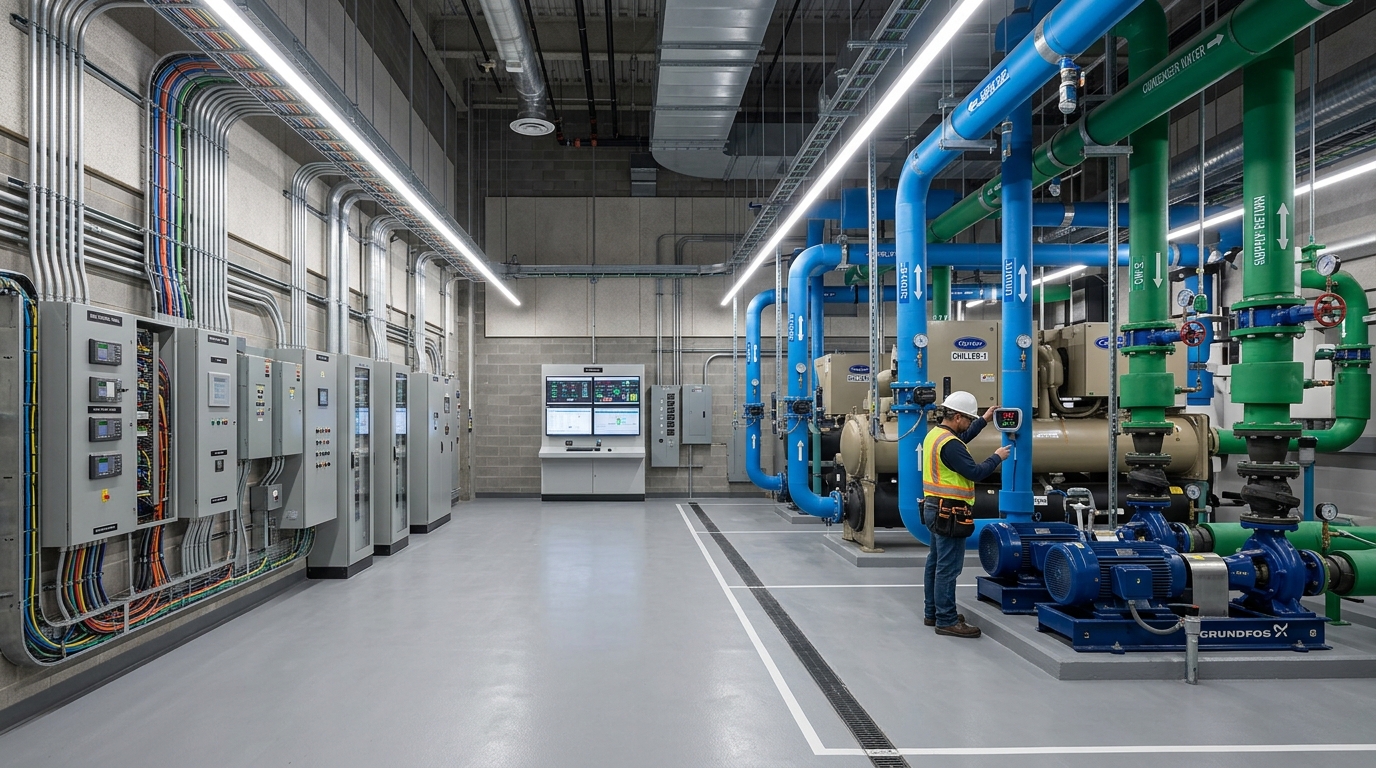
THE BUILDING BECOMES THE SYSTEM
Modern commercial, institutional, and industrial facilities no longer function as isolated mechanical or electrical silos. Instead, modern architecture encompasses numerous specialized systems that require coordinated monitoring, structured telemetry indication, and controlled operational visibility across day-to-day operations.
From HVAC plant status and electrical sub-metering to life-safety damper monitoring, access events, and environmental thresholds in mission-critical rooms, the facility operates most effectively when engineering interfaces allow disparate building elements to communicate through structured supervisory channels.
HORNET INFOTECH specializes in the ELV / ICT / controls / monitoring / integration layer within defined project specifications. HORNET does not independently design or engineer complete HVAC systems, mechanical chillers, electrical power generation, structural engineering, or general plumbing architecture unless specifically documented in a future verified project record.
Building Management Systems (BMS) in HORNET's field discipline establish the structured communication backbone, direct digital control (DDC) panel terminations, sensor networks, protocol translation gateways, and central workstation visualization that enable facility engineers to supervise complex environments with precision.
AUTOMATION REGISTER
FACILITY MONITORING
Centralized visibility of connected facility systems where required.
Establishes high-reliability telemetry collection across primary building infrastructure, aggregating discrete equipment contacts, analog sensor voltages, and serial communications into a synchronized supervisory framework.
- Equipment Status Contacts
- Dry Contacts & Digital Relays
- Analog 0-10V / 4-20mA Loops
BMS INTEGRATION
Interface and integration of building systems within defined project scope.
Configures microprocessor-based Direct Digital Controllers (DDC), modular I/O expansion racks, and field bus segments to coordinate multi-discipline building subsystems into a single operational architecture.
- Microprocessor DDC Units
- Field Bus Segments
- Protocol Translation Gateways
ELECTRICAL MONITORING
Monitoring interfaces for electrical systems where specified.
Provides continuous electrical parameter visibility by interfacing digital power sub-meters, main switchboard status contacts, UPS battery health telemetry, and automatic transfer switch (ATS) positions where required.
- Digital Multi-Function Energy Meters
- Main Panel Breaker Auxiliary Contacts
- UPS System Serial / SNMP Telemetry
MECHANICAL SYSTEM INTERFACES
Integration with selected mechanical systems where required by project design.
Interlinks chiller management panels, air handling units (AHUs), variable air volume (VAV) controllers, and fan coil units through standardized communication protocols to monitor operational states and alarm thresholds.
- Chiller Plant Gateway Interfaces
- AHU Fan Run/Trip Status
- VAV Actuator Position Telemetry
SECURITY INTEGRATION
Security and access events presented through facility monitoring where supported.
Interfaces physical access control controllers and perimeter intrusion alarms with central facility management, displaying forced-entry events, emergency door unlock states, and barrier positions on facility floor plans.
- Access Controller Event Gateways
- Emergency Break-Glass Monitored Contacts
- Turnstile & Barrier Status Relays
FIRE / LIFE-SAFETY INTERFACES
Fire alarm status and related interfaces according to approved cause-and-effect design.
Integrates dry-contact event triggers and supervised relays with main Fire Alarm Control Panels (FACP) to track zone alarm locations, trigger life-safety damper positions, and initiate HVAC shutdown in strict accordance with approved life-safety matrices.
- Supervised FACP Alarm Contacts
- Fire Damper Limit Switch Monitoring
- Smoke Evacuation System Interlocks
ENVIRONMENTAL MONITORING
Temperature, humidity, water leak and other environmental monitoring where specified.
Monitors ambient atmospheric variables and liquid intrusion in sensitive operations zones, including server rooms, electrical substations, archives, and UPS battery enclosures via high-accuracy sensing hardware.
- Dual Temp/RH Electronic Transmitters
- Linear Water Leak Detection Cables
- Precision Differential Pressure Sensors
CENTRAL SUPERVISION
Unified facility visibility where the project requires centralized supervision.
Delivers high-clarity graphical human-machine interface (HMI) workstations, multi-screen facility operations console layouts, alarm prioritization engines, and auditable event logging for building engineering personnel.
- Graphical Dynamic HMI Workstations
- Alarm Priority Management Console
- Historical Chronological Event Logging
REPRESENTATIVE FIELD PLATES
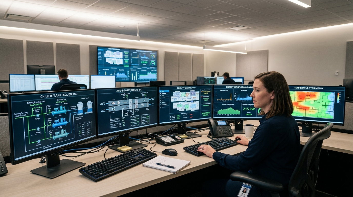
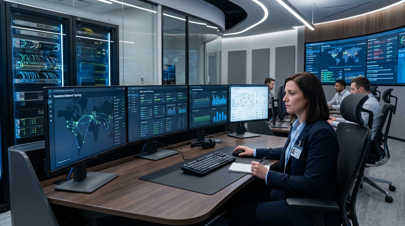
BUILDING OPERATIONS CENTRE
Architectural building operations environment configured with multi-screen supervisory workstations, facility alert consoles, and centralized system overview displays.
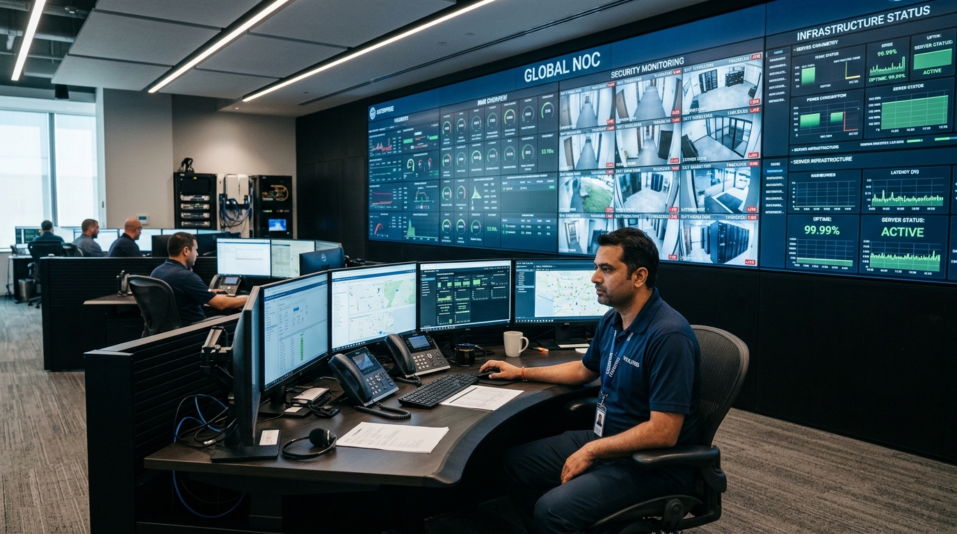
BMS / FACILITY CONTROL ROOM
Technical control room installation integrating status telemetry from connected facility subsystems, network supervisory servers, and operator response terminals.
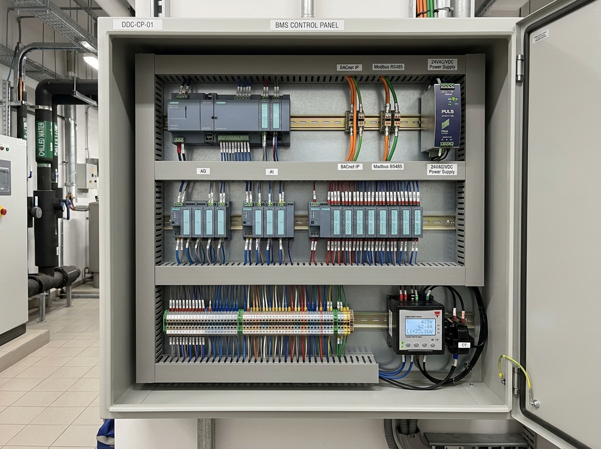
MECHANICAL PLANT INTERFACE
Enclosed industrial DDC automation panel housing microprocessor controllers, analog/digital I/O modules, 24V DC power distribution, and communication interface gateways.
ELECTRICAL / POWER MONITORING
Electrical room monitoring interfaces linking digital energy meters, breaker auxiliary status contacts, and power distribution telemetry over serial/IP communication networks.
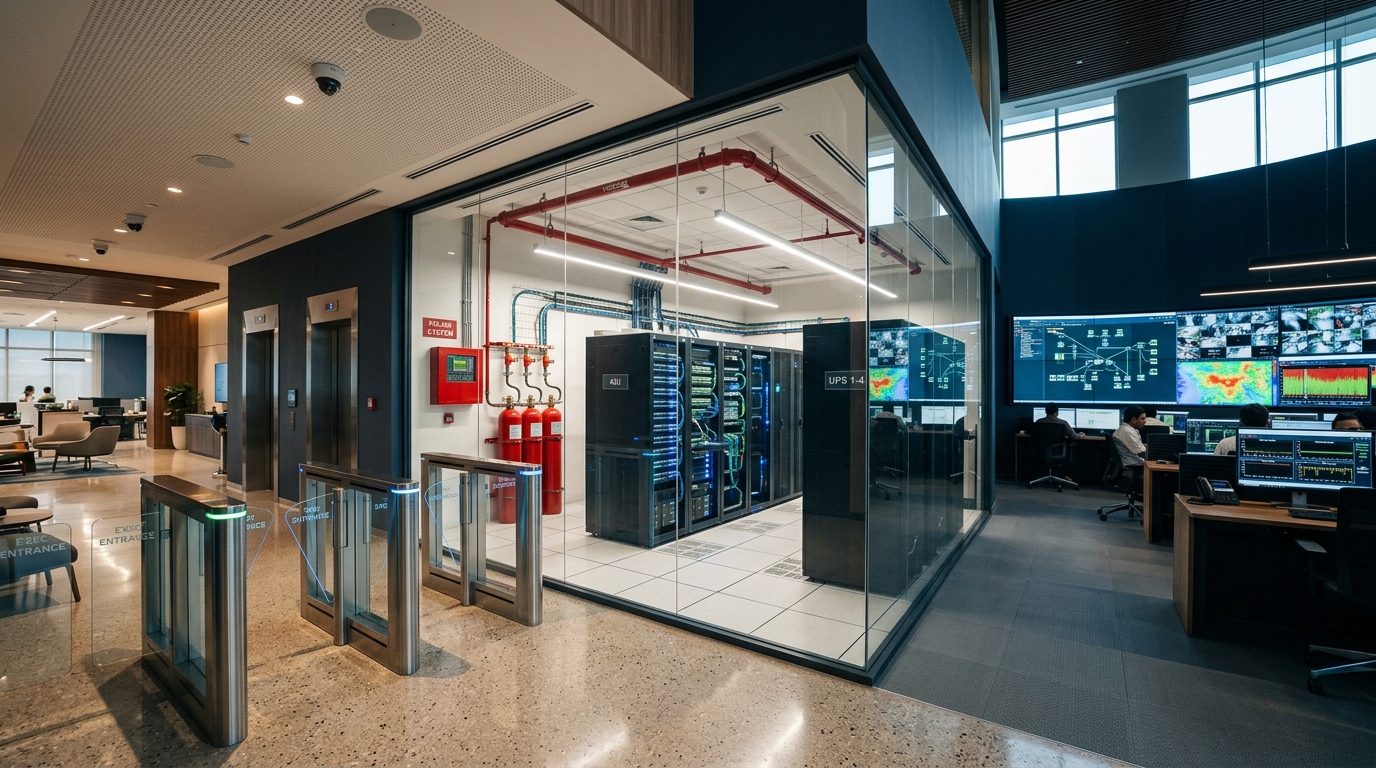
CRITICAL ROOM ENVIRONMENTAL MONITORING
High-density sensor integration across server and hub rooms tracking ambient temperature, humidity thresholds, sensing-cable water detection, and room status relays.
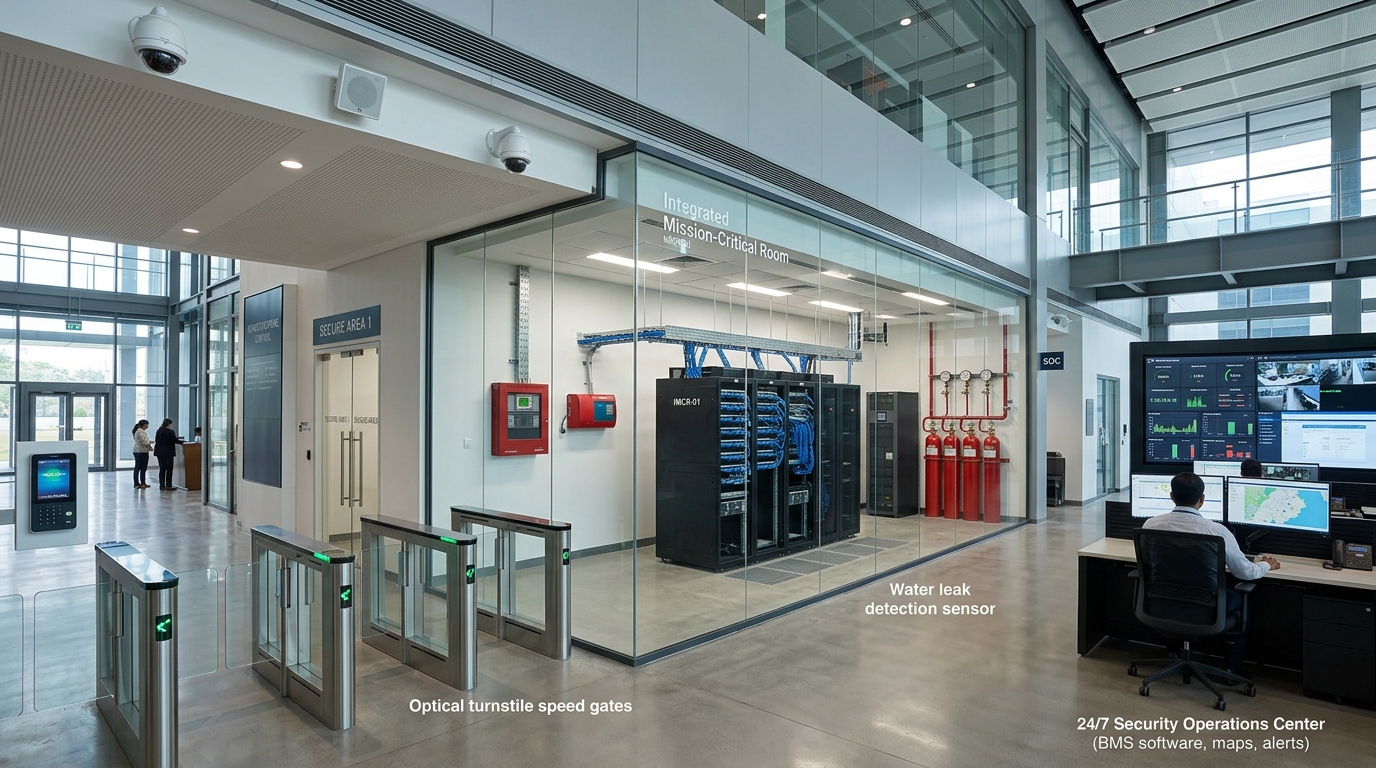
INTEGRATED FACILITY SUPERVISION
Commercial facility architecture showing spatial distribution of connected building subsystems coordinated through a structured ELV/ICT monitoring and automation backhaul.
ENGINEERING SCOPE & DELIVERY MATRIX
HORNET follows a disciplined lifecycle framework for BMS and automation integration. The specific stages deployed depend entirely upon the approved project engineering scope, MEP coordination, and client operational requirements.
SITE SURVEY
Physical audit of plant rooms, risers, panel locations, and cable path availability.
SYSTEM REQUIREMENTS
Identification of monitoring points, operator workstations, and integration standards.
POINT / SIGNAL MAPPING
Preparation of comprehensive hardware and software input/output (I/O) schedules.
INTERFACE DEFINITION
Coordination of communication boundaries with mechanical, electrical, and life-safety OEMs.
CONTROL ARCHITECTURE
Design of field bus segments, supervisory network topologies, and server redundancy.
NETWORK COORDINATION
VLAN allocation, IP addressing schemas, and protocol gateway routing coordination.
PANEL INSTALLATION
Assembly, wiring, terminal labeling, and physical mounting of DDC automation enclosures.
FIELD SENSOR INTEGRATION
Mounting and termination of temperature, humidity, pressure, and flow transducers.
SYSTEM CONFIGURATION
Programming of DDC control loops, alarm threshold triggers, and timing sequences.
GRAPHICS / INTERFACE
Drafting dynamic facility floor plans, plant schematics, and equipment popups.
INTEGRATION TESTING
Multi-system verification confirming signal integrity across third-party equipment gateways.
TESTING & COMMISSIONING
End-to-end point-to-point loop checks, sensor calibration, and sequence simulation.
DOCUMENTATION & HANDOVER
Delivery of as-built single lines, cause-and-effect sheets, and operations manuals.
AMC / LIFECYCLE SUPPORT
Periodic sensor calibration, software backups, and preventative controller audits.
SYSTEM CONVERGENCE SCHEMATIC
FACILITY SUPERVISION & BMS CORE
Centralized operator console, supervisory servers, historical event registers, and dynamic visual building graphics.
MECHANICAL / HVAC
Chillers, AHUs, VAVs & Fans
ELECTRICAL MONITORING
Sub-meters, Breakers, UPS Telemetry
SECURITY & ACCESS
Door forced, Reader alerts, Gates
FIRE / LIFE SAFETY
FACP Alarm state, Damper relays
ENVIRONMENTAL SENSORS
Temp, Humidity, DP transmitters
WATER LEAK DETECTION
Linear sensing cables, Critical rooms
CRITICAL ROOM PROTECTION
Server rooms, Hub rooms, Electrical LT
NETWORK INFRASTRUCTURE
Managed switches, Fibre backbone, VLANs
ARCHITECTURAL FACILITY ZONES
MAIN BUILDING / FACILITY AREAS
Primary commercial or institutional occupancies and public circulation corridors.
Floor temperatures, ambient humidity, common area lighting relays, life-safety damper positions.
Network DDC field panels, motorized damper switches, ambient space temp transmitters.
Provide baseline environmental stability and emergency life-safety damper coordination.
PLANT / MECHANICAL ROOMS
Centralized plant locations hosting primary chillers, pumps, boilers, and AHUs.
Chiller run/trip status, condenser pump differential pressure, supply air temperature, water flow.
Industrial DDC automation cabinets, immersion temperature thermowells, DP switches, analog valves.
Ensure centralized engineering visibility of primary thermal generation and distribution plant.
ELECTRICAL ROOMS
Main low-tension (LT) and medium-tension (MT) distribution rooms and capacitor banks.
Digital energy sub-meters, main air circuit breaker (ACB) trip contacts, transformer room temp.
RS-485 Modbus serial loops, digital multi-function meters, dry-contact auxiliary inputs.
Track power continuity, phase loading balance, and electrical switchgear operating status.
SERVER / NETWORK ROOMS
MDF, IDF, and telecommunications distributor enclosures across building floors.
Precision air conditioning (PAC) run state, ambient temperature, humidity, water leak detection.
High-accuracy dual sensors, spot/rope water leak detection controllers, door contact switches.
Protect high-density ICT switching and structured cabling infrastructure against thermal or liquid risk.
SECURITY OPERATIONS (SOC)
Dedicated control facility supervising CCTV matrixing, access control, and visitor management.
Access control controller heartbeat, perimeter intrusion alert flags, barrier status relays.
Ethernet supervisory gateways, dry-contact alarm inputs, multi-monitor HMI terminals.
Coordinate physical access alarms with broader facility emergency and entrance workflows.
CRITICAL ROOMS
High-value archives, clean-agent suppression rooms, UPS battery banks, and medical labs.
Clean-agent cylinder release flags, aspirating VESDA smoke alerts, battery room ventilation flow.
Supervised relay modules, hydrogen sensor interfaces, gas discharge pressure switches.
Provide immediate annunciation of critical room life-safety and environmental threshold breaches.
PERIMETER / ACCESS POINTS
Pedestrian turnstile banks, vehicular barrier gates, and emergency exit egress routes.
Barrier gate positions, optical turnstile cycle count, emergency break-glass activation state.
Loop detector controllers, door position monitoring switches, supervised fire-unlock contacts.
Supervise primary perimeter throughput and verify fail-safe emergency egress release status.
COMMON / CIRCULATION CORRIDORS
Public lobbies, elevator vestibules, emergency stairwells, and egress passageways.
Stairwell pressurization fan run state, emergency egress lighting relays, public address speaker lines.
Stairwell differential pressure sensors, 100V line supervision modules, DALI lighting routers.
Maintain safe egress conditions during fire alarm activation and normal daily transit.
FROM FIELD DEVICE TO FACILITY VISIBILITY
FIELD DEVICE
Physical instruments converting atmospheric or mechanical states into analog signals.
- Temperature Sensors
- Differential Pressure
- Water Leak Cables
- Dry Contact Switches
TERMINATION / IO
Structured DIN-rail marshalling cabinets isolating and organizing raw field wiring conductors.
- Terminal Blocks
- Surge Suppressors
- Analog Inputs (AI)
- Digital Inputs (DI)
DDC CONTROLLER
Distributed processing panels executing independent control loops and digitizing sensor metrics.
- Microprocessor Core
- Local Control Logic
- Non-Volatile Flash
- PID Loop Algorithms
FIELD BUS
Serial or token-passing networks interconnecting distributed automation panels.
- BACnet MS/TP (RS-485)
- Modbus RTU
- Daisy-Chain Topology
- Shielded Twisted Pair
GATEWAY / IP
High-speed routing hardware bridging serial controller field buses into the campus network core.
- Protocol Conversion
- BACnet/IP Gateway
- Modbus TCP/IP
- Ethernet VLAN Isolation
SUPERVISORY SERVER
Central host server running supervisory engine, real-time polling, and trend logging.
- BMS Core Software
- Historical Database
- Alarm Priority Engine
- ODBC/SQL Data Sync
OPERATOR WORKSTATION
High-resolution operator HMI consoles providing visual control and rapid diagnostic insight.
- Dynamic Floor Plans
- Equipment Schematics
- Alarm Annunciator
- Audit Trail Reports
INTEGRATION INTELLIGENCE RECORDS
Actual cause-and-effect sequences, interlock logic, and emergency responses are governed strictly by the approved project design, mechanical fire-safety matrices, and statutory municipal codes. The sequences below represent common integration methodologies.
FIRE ALARM & HVAC INTERFACE SEQUENCE
Supervised coordination between main Fire Alarm Control Panel (FACP) and air-handling subsystems during confirmed fire alarm events.
CRITICAL ROOM WATER LEAK DETECTION SEQUENCE
Fast-response liquid breach notification in raised-floor server rooms, telecommunication risers, and electrical panel environments.
ELECTRICAL POWER ANOMALY & ATS SEQUENCE
Real-time telemetry tracking when main grid power experiences interruption, phase loss, or transfer to standby diesel generators.
SECURITY FORCED DOOR & ACCESS INTEGRATION
Cross-system correlation between physical access control door switches, CCTV cameras, and facility operations consoles.
THE BUILDING IS DOCUMENTED AS A SYSTEM
INPUT / OUTPUT (I/O) SCHEDULE
Comprehensive registers enumerating every connected analog input, digital input, analog output, and digital output point.
POINT MAPPING REGISTER
Hardware and software cross-reference mapping field sensors to controller channel addresses and supervisory tags.
CONTROL SYSTEM SCHEMATICS
Architectural riser drawings illustrating controller communications, power feeds, panel locations, and backbone routing.
PANEL GENERAL ARRANGEMENTS (GA)
Detailed dimensional layouts of DDC enclosure internal DIN-rail components, power supplies, and field terminal strips.
TERMINAL WIRING DIAGRAMS
Point-to-point conductor schematics indicating terminal block numbers, cable wire codes, and surge protection terminations.
INTERFACE CONTROL MATRICES
Explicit boundary registers defining electrical, mechanical, and fire-alarm demarcation points across third-party equipment.
CAUSE & EFFECT LOGIC SHEETS
Documented behavioral matrices recording interlock actions, alarm priorities, fan shutdowns, and automatic responses.
NETWORK ADDRESSING SCHEDULE
Systematic register of MAC addresses, BACnet device IDs, IP addresses, subnet masks, and VLAN IDs for all controllers.
SYSTEM INTEGRATION MANUALS
Operator reference documentation providing user guides for the graphical HMI, alarm acknowledgments, and trending tools.
TESTING & COMMISSIONING REPORTS
Signed end-to-end point verification checklists, loop calibration certificates, and multi-system failover test logs.
AS-BUILT SCHEMATIC DRAWINGS
Final certified AutoCAD drawings reflecting exact as-installed cable pathways, sensor coordinates, and panel placements.
PREVENTATIVE MAINTENANCE AUDITS
Structured service guidelines, sensor recalibration timetables, software backup procedures, and controller health checklists.
VERIFIED BMS / AUTOMATION PROJECT RECORDS
COMMERCIAL & INSTITUTIONAL ARCHIVE DOSSIERS RESTRICTED
Hornet Infotech enforces a strict data integrity policy across its public web repositories. In accordance with enterprise non-disclosure agreements (NDAs) and institutional facility security protocols, verified Building Management Systems (BMS) and automation project dossiers are released only following formal client declassification and engineering audit.
Organizations requiring verified reference architectures, credentialed past performance, or project-specific capability statements may request credentialed documentation through our technical consultation desk.
ARCHIVAL BASELINE METADATA
COMMUNICATION STANDARDS
HARDWARE & PANELS
TRANSDUCERS & SENSORS
GOVERNANCE & AUDIT
ENGINEERED SYSTEMS
BMS & Building Automation
Centralized facility telemetry & DDC panel integration.
Water Leak Detection (WLD)
Linear sensing cables for critical room protection.
Fire Alarm Systems
Addressable detection panels & life-safety interlocks.
CCTV & IP Surveillance
Enterprise visual monitoring & VMS recording servers.
Access Control Systems
Turnstiles, smart readers, and monitored door hardware.
Online Modular UPS Systems
Power backup continuity & electrical monitoring.
Data Centres & Hub Rooms
High-density containment & environmental telemetry.
AMC & Lifecycle Support
Preventative sensor calibration & engineering support.
RELATED DISCIPLINE ARCHIVES
SECURITY & ACCESS
Access control matrices, IP surveillance clusters, speed gates, and SOC environments.
FIRE & LIFE SAFETY
Addressable detection loops, clean-agent suppression, VESDA, and voice alarm evacuation.
NETWORK & DATA
Structured Cat6A copper cabling, single-mode optical backbones, and enterprise routing.
DATA CENTRES & HUB ROOMS
Whitespace containment, modular online UPS, environmental monitoring, and WLD.
AV / VIDEO WALLS / CONFERENCING
SOC display walls, boardrooms, conferencing codecs, and digital signal processors.
MISSION-CRITICAL INFRASTRUCTURE
Fault-tolerant 2N power topologies, localized gas flood, and continuous supervision.
CONTROLLED PUBLICATION PIPELINE
PROJECT DOCUMENTATION
Compilation of signed commissioning certificates, single-line schematics, and equipment registers upon operational handover.
TECHNICAL VERIFICATION
Internal engineering audit verifying as-built accuracy, interface boundaries, and subsystem scope demarcation.
CLIENT CLEARANCE
Formal client security review and redaction of sensitive identifiers, asset tags, and proprietary network addresses.
PUBLIC ARCHIVE ENTRY
Release of declassified dossier into the public Hornet Infotech Project Archive with permanent archival indexing.
REQUEST TECHNICAL CONSULTATION
Engage Hornet Infotech engineering specialists for technical review, system architecture, point schedule definition, or integration specifications for your facility.