
SECURITY SYSTEMS.
CONTROLLED ENVIRONMENTS.
A dedicated field archive for HORNET INFOTECH security and access engineering work, including electronic security infrastructure, surveillance, controlled access and integrated perimeter systems.
SECURITY AS INFRASTRUCTURE
Security systems are engineered as part of the physical and operational environment rather than treated as isolated devices.
In high-density commercial, institutional, and mission-critical facilities, physical security requires deep architectural integration with building pathways, pedestrian circulation flows, and electrical low-voltage (ELV) networks. An isolated surveillance camera or stand-alone card reader cannot provide coherent site defense without coordinated containment, secure power backup, and multi-tier authentication logic.
HORNET INFOTECH approaches security systems engineering across comprehensive facility zones—spanning the outermost site perimeter, automated vehicular gates, pedestrian concourses, controlled core doors, and high-security technical enclaves. Each subsystem is engineered for deterministic fail-secure behavior, continuous network availability, and structured coordination with life-safety protocols.
SECURITY SYSTEM REGISTER
An editorial register of the electronic security subsystems designed and integrated by HORNET INFOTECH. Subsystem deployment is project-specific and adapted to architectural geometry and client operational requirements.
CCTV & IP SURVEILLANCE
IP cameras, recording infrastructure, video management and monitoring architecture.
ACCESS CONTROL
Controlled doors, authentication, readers, controllers and associated security interfaces.
PERIMETER & VEHICLE ACCESS
Perimeter surveillance, controlled vehicle movement and gate systems.
SECURITY OPERATIONS
Monitoring environments, video display and operator-facing infrastructure.
REPRESENTATIVE FIELD PLATES
Visual reference plates demonstrating typical security topologies, entrance architecture, and monitoring environments. Photographic assets serve strictly as illustrative art direction and do not represent documented client installations.
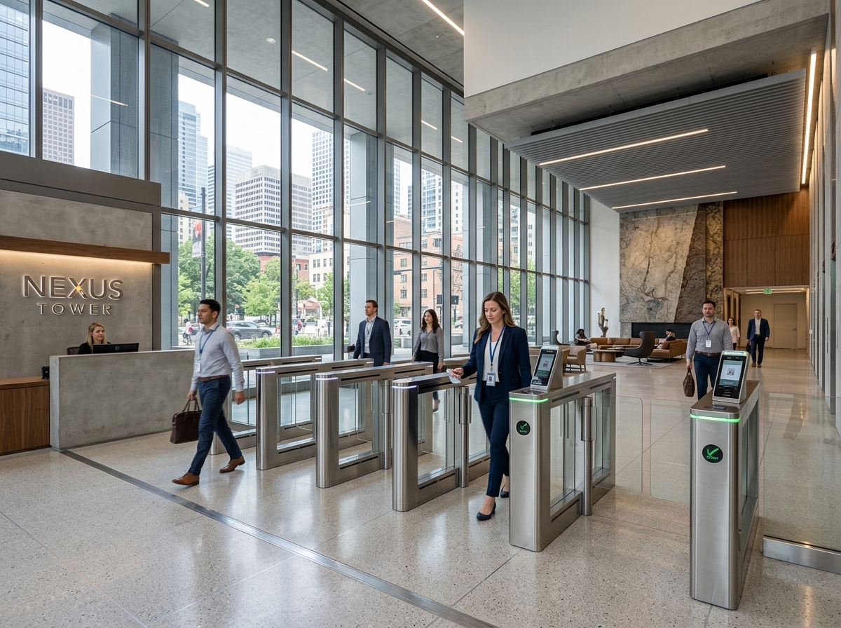
Multi-lane portal layout incorporating motorized barrier arms, automated ANPR cameras, and anti-tailgating turnstile banks.
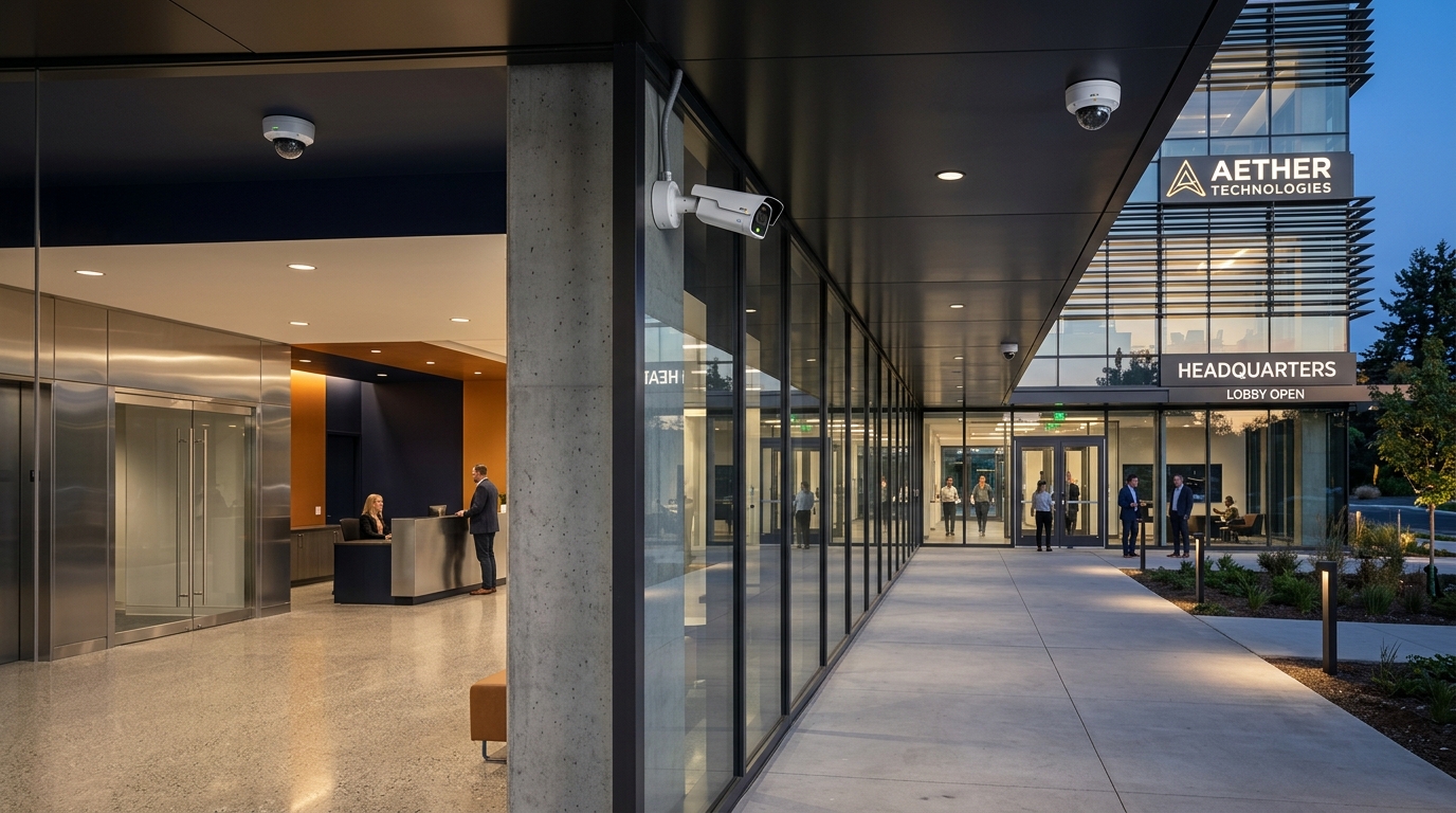
High-resolution IP surveillance cameras with analytics, PoE switching, and enterprise NVR/SAN storage retention.
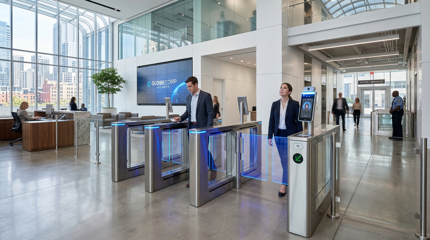
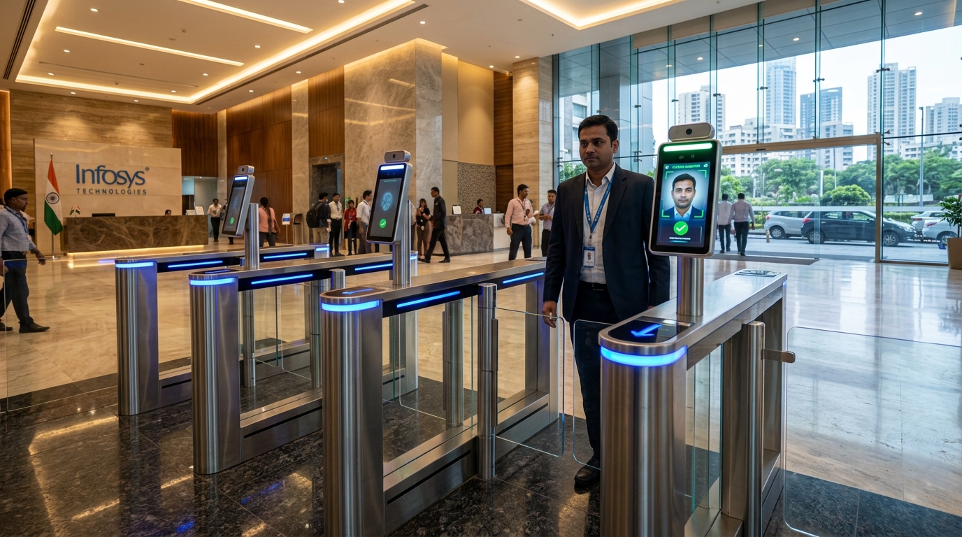
Integrated flap turnstiles, optical speed lanes, contactless RFID/biometric readers, and fail-secure door controllers.
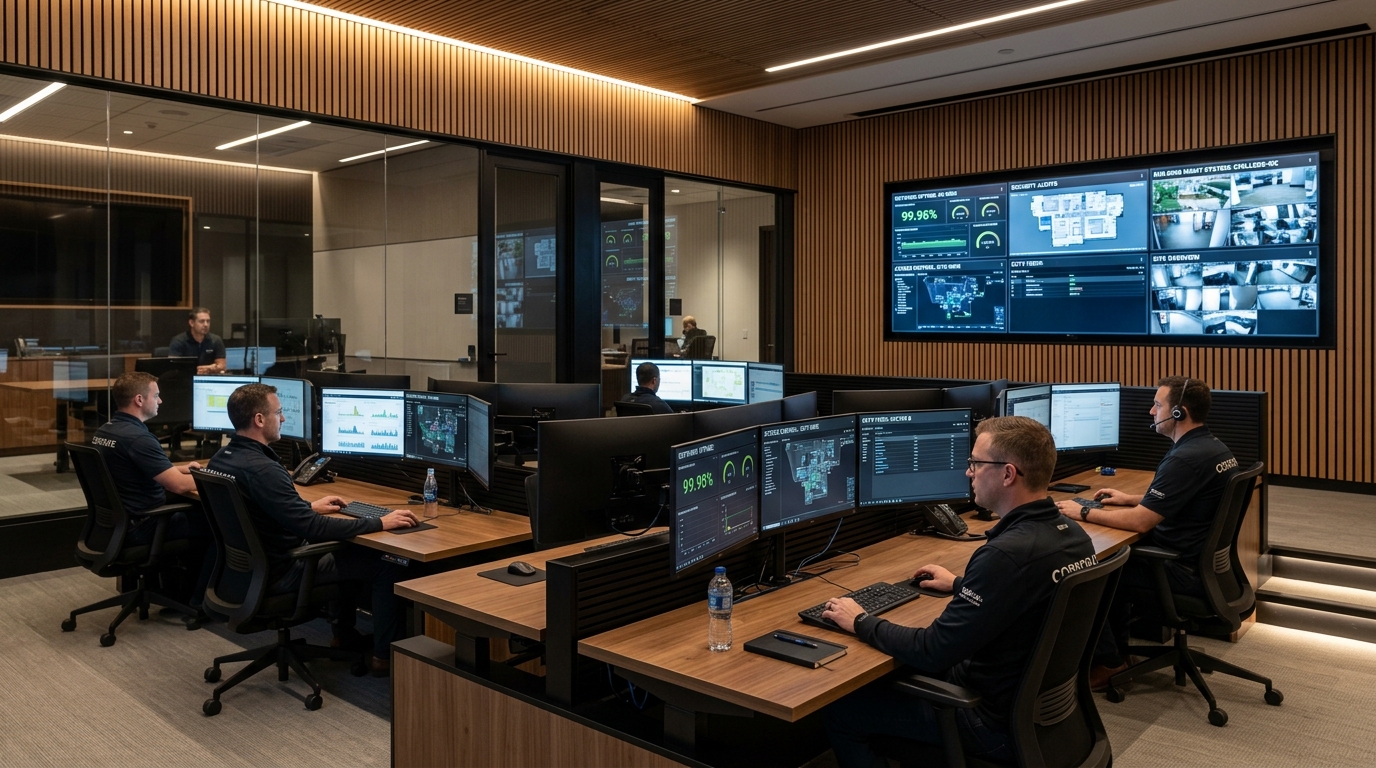
Dedicated operator consoles, multi-screen matrix feeds, unified VMS clients, and automated alarm pop-up dispatch.
Crash-rated automated bollards, motorized sliding gates, beam sensors, and long-range perimeter optical surveillance.
ENGINEERING SCOPE
The engineering delivery matrix below outlines HORNET INFOTECH's end-to-end service capabilities across security infrastructure lifecycle stages. These represent corporate capabilities and are not claims that all were delivered on any individual project.
SITE SURVEY & ENGINEERING
Line-of-sight analysis, lux-level optical surveys, pedestrian chokepoint profiling, and physical containment pathway mapping prior to layout drafting.
SYSTEM DESIGN
Preparation of single-line diagrams, camera cone-of-vision coverage modeling, network bandwidth / storage calculation, and door elevation details.
EQUIPMENT & MATERIAL SELECTION
Evaluation of enterprise-grade IP cameras, ONVIF/NDAA-compliant hardware, contactless credentials, motorized speed lanes, and hardened PoE switching.
SUPPLY & INSTALLATION
Installation of rigid MS/GI conduits, Cat6A structured cabling, optical distribution racks, field sensor terminations, and portal turnstile integration.
NETWORK / SYSTEM INTEGRATION
VLAN security partitioning, VMS server clustering, fail-safe fire alarm trip relays, access elevator dispatch protocols, and centralized time syncing.
TESTING & COMMISSIONING
Comprehensive loop insulation checks, reader response time validation, emergency door fail-safe release drills, and endurance stress-testing.
AMC & LIFECYCLE SUPPORT
Comprehensive preventive maintenance visits, camera lens realignment and cleaning, firmware security patches, database indexing, and round-the-clock priority SLA breakdown attendance.
SYSTEM CONVERGENCE
A visual flow mapping the progression from raw field physical sensors to centralized monitoring and facility-wide cross-system interfaces. Inter-system integrations operate strictly where project design requires.
CAMERA / ACCESS DEVICE
Edge IP sensors, smart credentials, optical barriers, push buttons, magnetic switches.
FIELD NETWORK
Hardened PoE switches, Cat6A shielded drops, and single-mode optical riser backbones.
CONTROL / RECORDING
Redundant VMS recording servers, RAID SAN storage, and multi-door access controllers.
SECURITY MONITORING
Centralized SOC workstation clients, real-time telemetry matrix, and automated event popups.
FACILITY RESPONSE
Operator dispatch, guard alert notifications, portal lockdowns, and event audit logging.
INTEGRATED SYSTEMS
Automated interlocks to fire alarm relays, BMS supervisory panels, and PA evacuation.
Hardware fail-safe release relays unlock emergency egress routes immediately upon confirmed fire panel alarm trip.
Dedicated surveillance VLAN partitioning with QoS video stream prioritization and 802.1x port security validation.
Zone-specific automated public address voice announcements triggered upon perimeter intrusion or tailgating events.
Matrix layout switching brings up active incident cameras and door state telemetry on operator video walls in real time.
Door open alarms, access count telemetry, and security power health status transmitted to building automation via BACnet/IP.
All interlocks adhere to fail-safe principles where human safety overrides property security protocols during life-safety emergencies.
REPRESENTATIVE FACILITY ZONES
An architectural spatial register detailing typical security design configurations across facility zones. Descriptions reflect representative engineering typologies and remain project-specific.
MAIN ENTRY / RECEPTION
PEDESTRIAN ACCESS PORTALVisitor verification, badging issuance, tenant credential flow, and aesthetic access control without creating lobby congestion.
Optical speed lanes, motorized flap turnstiles, visitor management kiosks, discreet wide-angle mini-dome surveillance.
Recessed floor trenches for power/data, under-counter duress triggers, and aesthetic barrier glass finishes.
PERIMETER & SECURITY GATE
OUTER DEFENSE BOUNDARYFirst-line vehicular filtration, perimeter intrusion deterrence, visitor pre-screening, and security guard booth monitoring.
Automated boom barriers, ANPR license plate cameras, long-range RFID windshield tags, and IR perimeter beam sensors.
Heavy-duty loop detectors, traffic signal lights, weather-proof enclosures, and underground concrete duct banks.
PARKING / VEHICLE ACCESS
TRANSIT & BASEMENTVehicle parking management, basement drive lane surveillance, speed regulation, and pedestrian exit corridor protection.
Vandal-resistant IK10 bullet cameras, ultrasonic parking occupancy sensors, crash bollards, and exit lane reader posts.
Overhead perforated cable trays, explosion-rated enclosures, junction boxes with IP66 weatherproofing.
CONTROLLED INTERIOR AREAS
FLOORS & CIRCULATIONTenant floor demarcation, elevator lobby containment, employee movement verification, and stairwell access regulation.
Contactless RFID smart card readers, indoor mini-dome cameras, electromagnetic locks, and push-to-exit buttons.
Concealed ceiling cable drops, door contact sensors, and localized fire release break-glass units.
RESTRICTED / HIGH-SECURITY
EXECUTIVE & VAULT ZONESSafeguarding confidential corporate archives, executive enclaves, cash handling vaults, and sensitive research suites.
Dual-factor biometric + PIN readers, anti-passback enforcement, continuous video recording, and door forced open alarms.
High-security electric mortise locks, armored door hinge conduits, and localized duress alarm sounders.
SERVER / NETWORK ROOM
TECHNICAL COREProtection of critical IT switching, VMS recording SANs, telecom demarcation risers, and access control power supplies.
Biometric access authentication, rack-level electronic locks, 360° panoramic fisheye cameras, and water/temperature sensors.
Clean-agent fire suppression interlocks, dedicated UPS power feeds, and air conditioning interlocks.
SECURITY OPERATIONS
COMMAND & CONTROLContinuous 24/7 surveillance monitoring, real-time alarm triage, perimeter patrol dispatch, and incident forensics.
Ultra-narrow bezel video wall matrix, multi-monitor client PCs, joystick PTZ controllers, and two-way intercom masters.
Ergonomic consoles, dedicated dual-bus UPS circuits, acoustically treated room envelope, and isolated management network.
SERVICE / BACK-OF-HOUSE
LOGISTICS & MEPLoading bay vehicle docking, service contractor verification, freight elevator transit, and facility maintenance corridors.
High-impact vandal-proof bullet cameras, heavy-duty shear locks, door prop sounders, and loading dock intercoms.
Surface-mounted galvanized GI conduit, heavy-duty crash rails, and weatherproof external junction enclosures.
VERIFIED SECURITY & ACCESS PROJECT RECORDS
Documented electronic security, video surveillance, and access control infrastructure delivered, commissioned, and handed over under formal contract governance.
AL-Karim University Campus ICT & ELV Infrastructure
Turnkey campus-wide ELV and ICT infrastructure across the 55-acre AL-Karim University campus in Katihar, Bihar, encompassing approximately 450–500 km of structured cabling, 35 km fibre infrastructure, 1,800+ data points, 1,000+ wireless access points, 500+ IP telephony endpoints, 8 flap barriers, data centre setup, AV conferencing, and environmental detection systems (VESDA, water leak detection, rodent detection).
eClerx Corporate Facility ELV & ICT Infrastructure (Phase 1)
Integrated ELV, electronic security, life safety, and network cabling infrastructure deployed for eClerx Chandigarh (Phase 1), supporting 216 CCTV surveillance cameras, a 340-device addressable fire alarm system, 170 PA speakers/units, 30 access-controlled doors, 1,500+ structured cabling data points, Novec clean-agent suppression, VESDA, WLD, and rodent detection.
eClerx Corporate Facility ELV & ICT Infrastructure (Phase 2)
Integrated ELV, electronic security, life safety, and network cabling infrastructure deployed for eClerx Chandigarh (Phase 2), supporting 178 CCTV surveillance cameras, a 215-device addressable fire alarm system, 120 PA speakers/units, 23 access-controlled doors, 1,000+ structured cabling data points, Novec clean-agent suppression, VESDA, WLD, and rodent detection.
In accordance with HORNET INFOTECH's data governance covenants, zero mock project entries or speculative installation claims are published. Verified field documentation dossiers are published under formal non-disclosure clearance.
TECHNICAL REFERENCE
Engineering reference standards, testing frameworks, and circuit baselines are applied strictly as required by individual facility design parameters and client specifications.
Surveillance resolution, lux performance, and reader credential architectures are engineered based on specific site risk classification.
Adherence to applicable Indian and international standards (e.g. NBC 2016, IEEE Ethernet, ONVIF) when mandated by project RFP specifications.
Single-server or clustered multi-node VMS topology, localized SAN storage, and access controller distributed intelligence tailored to scale.
Rigorous SAT/FAT execution, loop resistance audits, throughput trials, and emergency door release verification prior to operational handover.
ENGINEERED SYSTEMS
Explore the corresponding HORNET engineering solutions and technical system architecture.
CCTV & IP Surveillance
Enterprise-grade IP surveillance, AI video analytics, high-density SAN recording, and distributed VMS matrix architecture.
Access Control & Door Access
Smart credentials, multi-door IP controllers, biometric terminals, fail-secure electric locking, and visitor badging systems.
Speed Gates & Turnstiles
Motorized optical speed lanes, full-height perimeter turnstiles, anti-tailgating sensors, and rapid bi-directional pedestrian flow.
PUBLICATION PIPELINE
Genuine Security & Access project records will enter the public archive only after progressing through this formal verification sequence.
DOCUMENTATION
Compiling as-built conduit paths, camera schedules, IP allocation lists, controller terminal pinouts, and hand-over manuals.
TECHNICAL VERIFICATION
Senior engineering audit confirms circuit impedance, fail-safe drop relays, storage retention times, and network segmentation.
CLIENT CLEARANCE
Enterprise security officer and facilities director review to redact sensitive floor plans, camera IPs, and proprietary credentials.
PUBLICATION
Verified security field record is cleared for publication into HORNET INFOTECH's public documentary archive.
RELATED DISCIPLINES
Fire & Life Safety
Addressable fire alarms, VESDA air sampling, and clean-agent gas suppression.
Network & Data
Structured Cat6A copper, optical fibre risers, core switching, and enterprise Wi-Fi.
Data Centres & Hub Rooms
Server halls, thermal containment, online modular UPS, and environmental telemetry.
Mission-Critical Infrastructure
High-availability 2N power topologies, localized gas flood, and water leak sensing.
HORNET INFOTECH
Consult our security systems engineering team for turnkey electronic security design, access control schematics, site risk assessments, and enterprise CCTV specifications.